diy solar

diy solar

Need help with gauge wire, panel connection, and earthing.

Clembot

New Member
Joined
Apr 1, 2024
Messages
9
Location
Australia
Hi there!

I am currently trying to finalise my design for the system that will power our small house. We are fully off grid.

The system will be quite simple - compared to what some blokes here are running here and there - with initially 20 panels at 415w, 2 hybrid inverters from Growatt, and 10kw battery bank also from Growatt. ( final plan intends 30 panels. With 3 inverters and 15Kw battery total )

Now I have done a lot of reading through this forum and the beginners section and yet I can’t get to a conclusive solid answer for those 3 things:

My first query is regarding the connections of the panels. Being an AiO type inverter, I will run 1 string of 10 panels per inverter. Now the question remains Series or parallels-series? From what I can understand the Growatt inverter couldn’t support 10 panels in parallel, because the total A of each string panel would be above 120A so I figure series is the way to go, but maybe I am missing something or I could benefit from having a Para-series? At this point I am set for series, I am wondering if the length of the end cables have to be identical before they reach the inverter?
If that helps to answer the questions, the panels are all oriented and laying next to each other and of the same brand / type/ size on one big array.

My second question is regarding the gauge wire of the cable that will go from the inverters to the AC power board of the house.

The inverters and battery are located about 25 meters away from the house in they own little shed. I will have a breaker located next to the inverters, and then a long cable will run underground in a conduit to reach the house. I cannot be sure about what gauge would be safe to run here. From what I have read it seems that 16mm2 should do the trick but I was reading about the surge power on the inverter being 10kva so I wondered if my cable was too thin to handle that much or is it just the inverters capability…. Confused 🫤


My last question is regarding earthing - or grounding - has I have read a lot about the topic but still can’t make solid answers with it.

The earthing of the house I understand. A big long copper rod in the ground and a cable clamped or welded to it. But again what gauge?
Also nobody mentions anywhere if the DC circuit and AC circuit can share the same earth?
Do I need a separate earthing for the batteries/inverters/panels or do they have to link with the house’s earth?
Panel earthing is also never mentioned. Does the frame attached to the rails connected to a roof is enough to ground those or to they need to be also running an earth wire and if so does it follow the same rules - as in no loop - and therefore should meet with the earthing of the batteries and inverters?

I could run a long earth cable in the same duct as the AC load wire and have it run back to the shed to connect a common earth with the DC circuit if needed. But agin that seems odd.
Ideally I’d like to run my earthing directly out from the breaker that is located after the inverter and keep the earthing rod next to the solar shed. In that case is it ok to assume that the Ac load cable that runs underground is safe to carry the earth back with him?

Sorry of it is a bunch of silly question but I am getting mixed answers and since I am carrying out all the work my self I need to be certain.


Thanks for your help. I have tried to go though as much threads and beginners guide as possible but it seems that some things just get brushed off completely.

Hopefully I can get some definitive answers here, thanks
 
1 string of 10 panels is in series.

Your amps of 1 string is about 12. 10 awg seems to be a standard for panels, especially for the long run. I wouldn't go smaller than 12 awg.

6 awg seems to stick in my head for ground. Just guessing. Someone who knows grounding may be able to answer your grounding question.
 
My last question is regarding earthing - or grounding - has I have read a lot about the topic but still can’t make solid answers with it.

The earthing of the house I understand. A big long copper rod in the ground and a cable clamped or welded to it. But again what gauge?
Also nobody mentions anywhere if the DC circuit and AC circuit can share the same earth?
Do I need a separate earthing for the batteries/inverters/panels or do they have to link with the house’s earth?
Panel earthing is also never mentioned. Does the frame attached to the rails connected to a roof is enough to ground those or to they need to be also running an earth wire and if so does it follow the same rules - as in no loop - and therefore should meet with the earthing of the batteries and inverters?

Hopefully I can get some definitive answers here, thanks
You need to find someone from Australia to help you with the grounding (earthing) questions.
Your code requirements may be completely different from American, or European standards.
Hopefully one of your countrymen will see this thread, and can help out.
 
when stringing panels you have to watch the amps and the volts.

In series you are adding voltage together. Exceed the voltage rating of the MPPT and it will fry in short order. I realize it is Australia but the weather does cool off some. Panels are tested at 25c to determine voltage out. As you get cooler than that the voltage increases as does the current.

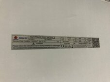
If you want more specific check on that topic, post a picture of the sticker from the back of a panel.
1714694944633.jpeg
 
You need to find someone from Australia to help you with the grounding (earthing) questions.
Your code requirements may be completely different from American, or European standards.
Hopefully one of your countrymen will see this thread, and can help out.
Hey man, thanks for your answer. The code? What code? 😛

I am building off grid - as in real off grid - no service roads, telephone, power or water - and also no code. I understand your position though and I see where you’re coming from. My question around earthing or grounding is more around the principle itself of the relation between the AC circuitry of the house and the DC circuitry of the solar system. Do they share the same ground?

As far as the code in Australia it’s a very close standard to the British one. A copper rod in the ground. Now I think I gave enough infos about the amount of power we will be generating / using in order to establish the need for establishing wire gauges. I was hoping someone here can maybe break it down to me as to what gauge to use for earthing.;;

That’s all
 
when stringing panels you have to watch the amps and the volts.

In series you are adding voltage together. Exceed the voltage rating of the MPPT and it will fry in short order. I realize it is Australia but the weather does cool off some. Panels are tested at 25c to determine voltage out. As you get cooler than that the voltage increases as does the current.

If you want more specific check on that topic, post a picture of the sticker from the back of a panel.
Hi thanks for your answer,

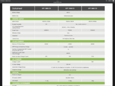
So I am well aware of this and I have calculated this knowing the data sheet of the inverter so I am fairly certain series is the way to go for my setup. Because those panels are 415 we can’t have more than 10. Per inverter
 

Attachments

  • 9B86B7F0-491D-4437-BF37-C00DD7C16720.png
    9B86B7F0-491D-4437-BF37-C00DD7C16720.png
    251.7 KB · Views: 3
Here, we DO NOT ground the DC voltage.
No conductors carrying DC voltage are connected to earth ground.
Edit: Like you, my Solar property has no governing authority either, but I still follow National Electrical Code for safety.
Some things I bend the rules on, but not on valid safety concerns.
 
Last edited:
Sorry - re-read your original post - answering what I can - deleted the nonsense I posted earlier.

Your panels are 32.0 volts each at 25c. Colder they are more warmer and they are less. Your MPPT can take 450v each circuit. You have 30 panels and you have 3 circuits for them. So 3 strings of 10 panels is a simple anwser wired in series. You are not missing anything. All panels in the string oriented the same direction and getting the same sun.

One thing to consider is pointing one string straight north or your optimal direction. Then point the other strings a bit east or a bit west. Kind of a blunted arrow point formation.

Grounding - in the US

I ground rod connected to the main panel with 6awg bare wire or larger. This is the only ground rod. No exceptions.
This ground is attached to the case of every piece of equipment. The racks for the batteries, the case of the inverter, a ground wire the same size as the pv wire is run along side the pvwires. The frames of the pv panels are grounded. The racking is attached to this wire. Anything metal you can touch.

What is never attached to the ground wire - either pole of any panel, either pole of the battery, any of the connections on the MPPT unless there is a ground screw on the side, none of the terminals to the electronics inside the MPPT.


Now, where it gets dicy is your australian power - are you doing 3 phase, 2 phase or single phase? Where the neutral and ground attaches to those is something you will need to know how to hook up or get local answers/talent.

Wire is sized by the rated amps, not by the surge load. Typical surge is only for a few seconds so it doesn't figure into the size. My yanky math says 67amps for 5k 208v . That is on the edge for 10mm, so 16mm is the right choice. 67mm for 89amps. Now here you derate cable in conduit so it might need to be bigger there.

Using a little AI help I come up with either 18.5mm or 24mm cable because it is conduit.
Hey Rob, thanks for this it’s very helpful.

Here in Australia we use 240v single phase.

Regarding to grounding, you have definitely answer my question but another comes to mine. The solar array is mounted on a structure that will have iron roof panels, as it is a very common material here. Since I am also making the roof to cover a container from rain and sunshine. Therefore, will the roof sheets also act as a ground body/mass or should they be insulated from the alu tails to prevent them from conducting?

Last question, why a buried cable in a conduct underground at 2 feet needs to be bigger? Is it because of the temperature or condensation?

Cheers
 
Here, we DO NOT ground the DC voltage.
No conductors carrying DC voltage are connected to earth ground.
Edit: Like you, my Solar property has no governing authority either, but I still follow National Electrical Code for safety.
Some things I bend the rules on, but not on valid safety concerns.
Hey mate, thanks for your answer! Where are you located roughly just out of curiosity?!

I try to stick to code for as long as it makes sens to me and my budget, sometimes it just doesn’t make any sense to follow it, sometimes I go a notch above And exceeds standards … it depends on the situation!

So no grounding of the dc but batteries and panels yes?
 
Hey Rob, thanks for this it’s very helpful.

Here in Australia we use 240v single phase.

Regarding to grounding, you have definitely answer my question but another comes to mine. The solar array is mounted on a structure that will have iron roof panels, as it is a very common material here. Since I am also making the roof to cover a container from rain and sunshine. Therefore, will the roof sheets also act as a ground body/mass or should they be insulated from the alu tails to prevent them from conducting?

Last question, why a buried cable in a conduct underground at 2 feet needs to be bigger? Is it because of the temperature or condensation?

Cheers

It is because wires are rated in free air for cooling. Confined in conduit burried or not the heat accumulates.

For your metal roof, if it is going to be in contact with the frames I would go ahead and connect the ground wire to it.

The idea is that you want all possible touch points to be at the same electrical potential. This way if you are standing on that roof and touch a panel you won't get shocked. You also want the shells of everything at the same potential for when lightning strikes. That way they all raise and lower together and there is no path through equipment to ground, just around it. This is also why you do not connect the negative of the battery or the negative of the panels to your ground.
 
Hey mate, thanks for your answer! Where are you located roughly just out of curiosity?!

I try to stick to code for as long as it makes sens to me and my budget, sometimes it just doesn’t make any sense to follow it, sometimes I go a notch above And exceeds standards … it depends on the situation!

So no grounding of the dc but batteries and panels yes?
+1 to what robbob2112 said.
Anything with a metal frame is bonded by the grounding conductor to one main earth ground rod, usually at the main AC breaker panel.
 
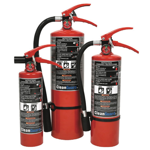
This was from the first link, it looks promising depending on cost


Or this

The downside of Halon and other automatic systems that smother fire is they can smother a person too, so automatic without some sort of interlock or disable switch for someone in the room to use is a bad idea. Were I to do it I would have something tied to a door sensor

And, I ordered some of these to test.
 
Last edited:
Back
Top