diy solar

diy solar

Top Balancing using SI-6048?

Disturbedfuel15

New Member
Joined
Aug 12, 2023
Messages
63
Location
Mich
Hello,

It appears I pulled a rookie-move and had my JK PB2A16s20p balancing turned on when the cells were at 70%, where they came from the factory. I didn't realize I was possibly doing harm... now I know. In any case, I have five of these BMS, five 48v 280ah packs. The cells are laser-welded together, so I cannot remove them and connect all batteries in parallel to pursue the recommended top balance settings. I'm also using two SI6048US on the latest firmware. They are talking to the BMS pretty well for the most part. I have the battery type as external lithium ion, so it gets all charging parameters from the BMS (I believe).

There are a few cells in a couple packs that charge faster than others, causing the charging to stop due to cell OVP.

What I've read is that nowadays with active balancers, like these have, with 2a balancing current, I may be able to top balance by just letting the BMS' do their thing. I don't know that I can make the SIs send a constant charge voltage, so I have a 10a 0-60v bench power supply coming, too. If I don't have to open it and I can return it, that would be terrific. I'd like to top balance using the SIs.

I'll post my current BMS settings here. The only difference I made this morning before posting is I upped the requested charge voltage to 3.5v from 3.45v, and I set the charge current max at 2.0a in hopes the cells don't drift too far apart under this smaller charge current. Looking at the BMS displays currently, I'm seeing between 1-2a of current, so the BMS are doing their job. Once all cells reach 3.5v and are within .0010v of eachother, I want to up it to 3.55v, then 3.6v, and then maybe call it good? How does that sound? I appreciate any responses tremendously. I'm here to learn. Thank you!
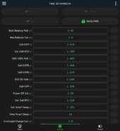
Screenshot_20240504_110659_BMS.jpg
 
I did a top balance with a JK-PB2a and an SMA SI5048 using SI6048US firmware and running closed loop Canbus, it was down to 0.002V deviation between cells yesterday..

Balance on is set to 3.45V,

Vol cell RCV 3.513

SOC-100% Volt 3.512

Cell OPRV 3.498.

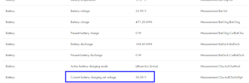
Reason for the higher Vol Cell RCV is that the SI5048 takes off 1V from the Canbus info sent to it by the JK and reports it as 55.2V for the 16 cell bank instead of 56.2.

So your 3.5V is not getting through to the SI as 56V but as 55V

All detailed in this thread

 
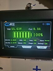
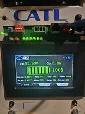
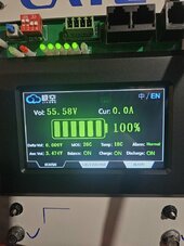
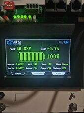
I'll add the current status of each 16s bank here. Now that I look at it, it seems everything cell is already pretty close, perhaps this 2a limit helped. Maybe it's when charging at 30a+ that it caused certain cells to charge faster. Anyway, in the future, I'm planning many cycles for these and I can't have that happen when charging at full capacity. I believe that means I still need to continue to top balance, albeit with a higher voltage already? 3.55v? It also seems like the biggest delta is between packs, not between cells.
20240504_111517.jpg20240504_111536.jpg20240504_111512.jpg20240504_111530.jpg20240504_111524.jpg
 
I did a top balance with a JK-PB2a and an SMA SI5048 using SI6048US firmware and running closed loop Canbus, it was down to 0.002V deviation between cells yesterday..

Balance on is set to 3.45V,

Vol cell RCV 3.513

SOC-100% Volt 3.512

Cell OPRV 3.498.

Reason for the higher Vol Cell RCV is that the SI5048 takes off 1V from the Canbus info sent to it by the JK and reports it as 55.2V for the 16 cell bank instead of 56.2.

So your 3.5V is not getting through to the SI as 56V but as 55V

All detailed in this thread

Thanks, I will try those parameters. It does seem I need to put the SI in standby before adjusting, or else it gets confused and shuts off when adjusting each BMS, no matter how quickly I try to adjust the RCV/etc. No big deal, just an observation I found. Thanks again.
 
Have you calibrated the voltage of each BMS, mine were not matching the SI but the digital meter was spot on to the SI so I calibrated to the digital meter when the battery was resting.

Calibrating the amps should be b=done under load but not really got that sorted yet, it goes off as the load drops and shows too much discharge overnight at low loads compared to the shunt linked to the SI.
 
I did a top balance with a JK-PB2a and an SMA SI5048 using SI6048US firmware and running closed loop Canbus, it was down to 0.002V deviation between cells yesterday..

Balance on is set to 3.45V,

Vol cell RCV 3.513

SOC-100% Volt 3.512

Cell OPRV 3.498.

Reason for the higher Vol Cell RCV is that the SI5048 takes off 1V from the Canbus info sent to it by the JK and reports it as 55.2V for the 16 cell bank instead of 56.2.

So your 3.5V is not getting through to the SI as 56V but as 55V

All detailed in this thread

Sorry for double quoting, but do you perhaps think that is a problem with 5048 and not the 6048? From Data Manager M Lite:
1714836726336.png
 
Thanks, I will try those parameters. It does seem I need to put the SI in standby before adjusting, or else it gets confused and shuts off when adjusting each BMS, no matter how quickly I try to adjust the RCV/etc. No big deal, just an observation I found. Thanks again.
I have yet to see that, even changing from one of the 3 working canbus protocols to another working one shows no glitches and the SI carries on.
 
Have you calibrated the voltage of each BMS, mine were not matching the SI but the digital meter was spot on to the SI so I calibrated to the digital meter when the battery was resting.

Calibrating the amps should be b=done under load but not really got that sorted yet, it goes off as the load drops and shows too much discharge overnight at low loads compared to the shunt linked to the SI.
I did not calibrate the voltage of each BMS. I did not know I had to do that and I do not know how to do that.
 
I will still set the SOC100/etc values to .001 lower than the previous, like I would have it if I were not top balancing. I didn't know how the SI would handle the RCV being .5v higher than the SOC100%. Let's see what difference that makes.
 
Mine is
I did not calibrate the voltage of each BMS. I did not know I had to do that and I do not know how to do that.
Easy, its on the 2nd page of the Windows/Bluetooth app. Look for Basic settings at the top of the page.

Calibrating Volts and next to that is the current volts it thinks the bank of 16 cells in total is.

Take an accurate meter and measure the bank volts at the 2 +/- lugs, then put that voltage in overwriting the current measurement. The voltage on the first page will change and all the 16 cell voltages changed to add up to the calibrated Volts.
 
You calibrate the Amps in the same way but under a heavy charge and using a DC clamp meter.
 
Post picks while they are still charging at the top voltage. All the packs should be at the same voltage, and cell delta under .010v
 
I will still set the SOC100/etc values to .001 lower than the previous, like I would have it if I were not top balancing. I didn't know how the SI would handle the RCV being .5v higher than the SOC100%. Let's see what difference that makes.
I suspect that SOC 100% voltage will trigger the SI to reduce the charge, I have always had it 0.001V below the RCV so have not tried it so its a guess. Next sunny day I will test to see.
 
Mine is

Easy, its on the 2nd page of the Windows/Bluetooth app. Look for Basic settings at the top of the page.

Calibrating Volts and next to that is the current volts it thinks the bank of 16 cells in total is.

Take an accurate meter and measure the bank volts at the 2 +/- lugs, then put that voltage in overwriting the current measurement. The voltage on the first page will change and all the 16 cell voltages changed to add up to the calibrated Volts.
I honestly did not know this was a thing. I had no idea what it did. Thank you for this. It is easy and I will do it now. I also have a fluke clamp meter if I need to do the amp calibration in the future....
 
Disable comms until you have it all top balanced.
I suspect this would mean reconfiguring the battery type in the SI as lead acid. I'd have to do research on this, as I did not delve into the lead-acid structure. Are you sure this is necessary? If BMS controls the charge, couldn't I use the BMS to request whatever I want from the inverter? Thanks for your help!
 
I would calibrate the voltage for each pack, then see how close they are. I suspect they will be close enough they will top balance without resetting the SI.
 
I would calibrate the voltage for each pack, then see how close they are. I suspect they will be close enough they will top balance without resetting the SI.
WOW! They are all the exact same voltage! I made sure to disable charge/discharge before measuring each one. You've once again saved me a lot of time, thanks.

I think I'm going to go ahead and up the RCV again and let them continue to do their thing.
 
I suspect this would mean reconfiguring the battery type in the SI as lead acid. I'd have to do research on this, as I did not delve into the lead-acid structure. Are you sure this is necessary? If BMS controls the charge, couldn't I use the BMS to request whatever I want from the inverter? Thanks for your help!
What you want to do is charge until bms cuts out.
Hold voltage under the cutoff as cells balance.
Slowly increase in 0.1v increments until you reach 57.6v, or bms limit.

Can't do that with bms controlling.

Then your cells will be balanced. Bms cutting out prevents cells from really balancing.
 
Back
Top