diy solar

diy solar

Building the sickest ® VAWT ever. Brilliant minds unite please!!

arggggggg. this will never work. how can we expect sellers of the all new and improved PMAs that are just waiting to be sold onto consumers less witty than we are.

They are never going to blow up car lights in order to have their begammagahas bejammas new baby milk all new improved PMA any kind of realistic measurement for us consumers to base decisions on.
 
now I am sure most of us know what I am referring to when I use these weird words to describe a quality to a thing.

But for those that have not yet been delighted to this weirdness

 
So here is my proposition for the CML.

I am thinking along the lines of. (amp(CC) * vAC(OC)) / (Hz(OC) / Hz(CC)) = CML expressed in pseudo watts.

Now that is called a mamba bejamba.... mehamba mehjammabaja! :)
 
Last edited:
Ok so I just realized that I am on the wrong track with this CML forumula.

You see that I can configure the motor to adjust it's torque just so that there is not really a noticeable speeding up when opening up the coils.

It is called torque compensation or something to that effect which I of course have no way of understanding yet other than knowing that my proposition is still pseudo.

argggg

But come on gang! seriously. Let us work to something KISS
 
hahahha I know now what to do.

And it will get us all in shape as a bonus.

THe only real way to figure out the CML is to have us run the actual turbine that drives the PMA. And run as fast and hard as you can.

And then in my case I would drop before a single rotation. Now some amongst us here dear readers can maybe run more and harder.

Ohh wait!!. Hmmmm So this is also not a good idea to be able to compare apples to oranges. :) hahah (this joke was a setup. Of course I knew this from the get go)
 
arggggggg. this will never work. how can we expect sellers of the all new and improved PMAs that are just waiting to be sold onto consumers less witty than we are.

They are never going to blow up car lights in order to have their begammagahas bejammas new baby milk all new improved PMA any kind of realistic measurement for us consumers to base decisions on.
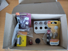
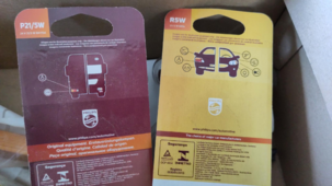
Ok so I found the car lamps that I did already have. Some 24V and some 12V. I tried to see if they require DC or can also work with AC on the back of the packs but it's either not stated or I lack the experience to dissern that.

1715079708208.png

1715079864887.png
So given that we are now going to use 3 of those coils I mentioned most recently in a delta setup I am hoping for a whole lot more of amps to flow this time.

So on the AC side I expect things to be wild no doubt. It is the DC side after the full bridge rectifier I am worried about given all these losses we have seen rather recent.

So if it is up to me I will not use the DC side at all while trying to give a rating to this PMA.

But I do really think it would help if you guys would still accept the results if I do.
 
So here is my proposition for the CML.

I am thinking along the lines of. (amp(CC) * vAC(OC)) / (Hz(OC) / Hz(CC)) = CML expressed in pseudo watts.

Now that is called a mamba bejamba.... mehamba mehjammabaja! :)
As to not scare off people with an actual knowledge of the subject too much, it is my intention to use the "Hz(OC) / Hz(CC)" part of the equation to tone things down again a little less "unexpected" when dealing with a CML.

So we now have an, for my knowledge level, arbitrary decision to make.

So lets assume the first parts solves to these 80 watts I have been boasting earlier. Now 80 is just tooo much for it to ever be accepted as a CML result in the MC(*cough* She)U standard.

So then I thought throw in some sanitation, based on the rotational speed and tone down that rather high number a bit.

Let us, just for the sake of working out the premise, take the Open Circuit Hz is 1 and the Closed Circuit is 0.5.
Then the result would be 1/.5 = 2
So then dividing the wattage we get from the first part is actually already going much lower.
So 80 / (1 / .5) = 40

But we could also do the switcheroo here in where we realize.
NEE!! it should be multiply the first part with the second part but then work out the second part with multiplication rather than division.
Like so:
"Hz(OC) * Hz(CC)"

Resulting in the CML formula becoming
CML(Watts) = (amp(CC) * vAC(OC)) * (Hz(OC) * Hz(CC))
So 80 * (1 * .5) = 40

Ok truth be told. I am being loud about this process as it is my first ever attempt to trying to establish some consensus while throwing in some math and physics. So I would like it to make a bare bone minimum of sense for one to be able to either reject or allow for. Hence me laying bare the thought process behind it.

I have so little attention span that I am not even sure I did this correct to begin with :)
 
Last edited:
nah not delta . star. it is not the voltage levels I am worried about being able to get at. It is the amps that should be wicked(TM). Thus with my limited knowledge I arrive at a star configuration.

But left or right. It is easy enough to try both and then see in practice how car lights actually explode!!

I am almost at a point in where I think we are going to need a high speed camera to record the exploding of car lights.

This is such nonsense. II think you all know already I like to practice showmanship a bit.


----


If only I had craftsmanship.
 
hoppa!!

my first ever 3 phase configured PMA

1715088166885.png

Yes I also see things so no need to seek nails at low tide.


But I am still so syco stoked about this.

I am going to focus now on getting this out of phase to near 120 degrees. As it is not humanly possible to get things 100% correct like on the drawing board.

Sure I also see the voltage difference and that tell me that not all coils are created/installed equal.
I know :) sue me :) haha let this please remain a joke for the fact that I am not flawless.
 
Last edited:
Incandescent lamps will be fine with either DC or AC. At 60 Hz, steady glow, but low frequency they may pulse to the beat.
Rectified AC, perhaps they will make some noise due to the harmonics, not sure.

Light bulbs start out at 1/10th the resistance their wattage & voltage suggests, increase to expected resistance when they reach operating temperature.
At low frequency, if they flicker significantly, I'd expect the resistance to vary somewhat. But maybe not a lot - I think TCR is relatively constant, resistance proportional to temperature. Emission (of light, electrons) I think is a log function, so slight cooling and slight decrease in resistance corresponds to significant decrease in light. Still plenty of heat, less efficient.
 
I finally figured out where all these losses are coming from.

I was using not only half wave rectifiers but also incredibly bad quality ones even though sold as legit bridge rectifiers.
Once again got burned buying on great market places and letting scammers get the best of me.

I am waiting for the single and 3 phase full bridge rectifiers to arrive. And even though from a legit seller and brand. Not even all that expensive anyway.

So fingers crossed I can show better results soon.
 
uggg. it seems there was nothing wrong with my old rectifiers all along.

You see the a new one arrived today. the 3 phase one and I went straight back into my evil lair to see if there would be a difference this time around.

And to my horror things were rather similar this time around.

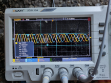
This picture has a lot of noise in the waveform but that is simply because the motor and it's drive are making the PMA vibrate. When I hand spin then things look smooth as a baby's buttocks.

1715349805793.png

I was just drawing the wrong conclusions when I read articles like this
TL:DR it shows pictures with differences between half and full wave rectification.
Now of course I did not read the formulas and most of the text. I am like an infant only drawn to images :)

So I should focus on what I am good at. Relentless testing/thinking about until I can understand it my self. and then continue.

You see. I know by now that the CML formula is wrong because it does not take into account the interaction level between electromagnetic field and the static magnetic field. That would mean that if I fine tune my coil in just the right way I could ramp it up reallllly high before it starts overheating. And the open circuit voltage would be stellar. resulting (when using the CML v0.000001) in a value that is soo far too high.

Too high because then when we hook up a load. Nothing happens as the coil cant produce a field strong enough to interact with the magnets at the slow speeds we want to turn at.

So I will reintroduce the gravity torque tests as a component in the formula to calculate the CML. Which I will probably rename to something like the CMPL. (Coil Magnet Power Limit)

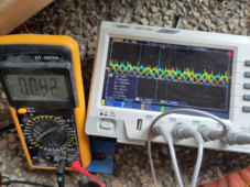
Also I need to get rid of this crap junk multimeters.. These values are also throwing me off track. You see they are such crap that when the Hz is low then their reading is soo far off from the one on channel 4 on the oscope.

But when I go 10 times faster then the multimeter is starting to show similar readings. So basically useless junk for what needs to be done here.
 
Last edited:
So all this above was to say that even though I met by brothers today over at the farmers defense force secret outdoors meeting, yet still being a well hidden and unknown lair to even their neighbors..
They were cool with the fact that we need some more time before it is time to help out the cause.

They showed me what toys of theirs they have in mind to come out and play to rip the PMA apart.

1715350521277.png
1715350531887.png


----

if they can :)


DISCLAIMER ALERT!! I am sure everyone knows that even though I took those images from these bad boy tractors today my self. I still want to make sure that this was just an open day as some cool farmers place that opened his doors for the kids to enjoy.

So nothing defense force related going on there what so ever.

I just like spicing up stories.

I have always known that I wanted to become a writer. And I missed the off ramp to that direction so it seems
 
Last edited:
I am not sure if I can copy an image from another source directly. So I will try and insert the direct link.
This is what I though I should see based on that article I shared just now.

Yet I always seem to get

So either I am still buying the wrong components as we should not buy this

I did notice it does not state FULL in bridge rectifier. So this is just a bridge rectifier rather than a full bridge rectifier yes?
 
Please remove as This warning regarding my joke about the tractors should have been made on the actual post about the tractors. not here. . Thank you
:(
 
Last edited:
I am not sure if I can copy an image from another source directly. So I will try and insert the direct link.
This is what I though I should see based on that article I shared just now.

Yet I always seem to get

So either I am still buying the wrong components as we should not buy this

I did notice it does not state FULL in bridge rectifier. So this is just a bridge rectifier rather than a full bridge rectifier yes?

The part shows this:

1715353423437.png

I think if you have an AC source with 3 lines driven relative to neutral/ground, voltage from (+) terminal to ground will have the higher ripple.

Voltage between (+) and (-) will have lower ripple, but its common mode bounces up and down relative to ground. That is what a VFD would operate from.

Used with your isolated alternator, I think voltage is only available between (+) and (-), so should be lower ripple.
 
So either I am still buying the wrong components as we should not buy this
I did notice it does not state FULL in bridge rectifier. So this is just a bridge rectifier rather than a full bridge rectifier yes?
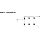
That is a full wave, three phase rectifier. The product page you showed has a hookup diagram:

36MT160_VIS.png


This is the same as the diagram on the tutorial page you posted.

You can test the diodes using your meter and referring to the diagram.
 
Voltage between (+) and (-) will have lower ripple, but its common mode bounces up and down relative to ground. That is what a VFD would operate from.
In other words, you cannot tie the AC neutral to the DC ground. Doing so would reduce the rectifier to half wave.
 
That is a full wave, three phase rectifier. The product page you showed has a hookup diagram:

36MT160_VIS.png


This is the same as the diagram on the tutorial page you posted.

You can test the diodes using your meter and referring to the diagram.
hahah bro :) Testing diodes is way above my pay grade :)

I think I would like to be hand held, as I am not sure how long it would take for me to get through all of the above, Just to get to a wave like this.

power98.gif


then things will become logical again for me as I have been lead to believe that 3 phase will lead to bliss :) And currently, by my experience, it leads to confusion :)
 
Back
Top