clint0n
New Member
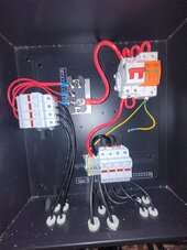
My system was working great since installation, until today at peak time when my inverter stopped charging, I came into the electrical room, and smelled a burnt smell. All the strings are producing the correct voltage, but once I flip my circuit breaker on in the combiner box, the lines drop from 160vdc to 2.5v and the output to the inverter reads 1vdc. I'm thinking it's the mds module or the circuit breaker itself. Any help would be appreciated.