diy solar

diy solar

3 EASUN parallel hybrid to 2 DEYE hybrid migration

liberumyu

New Member
Joined
Jul 2, 2022
Messages
68
Hi all.

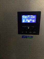
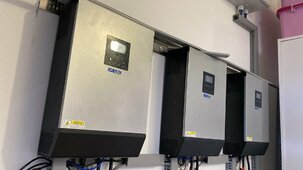
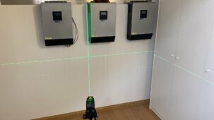
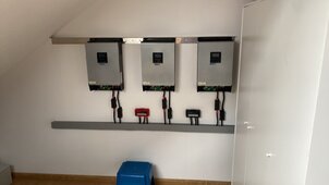
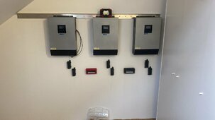
I have decided to migrate my system from EASUN to DEYE and from attic to garage.

Drivers for this change are hot conditions in attic during summer requiring AC to run most of the day and EASUN inverters switching to bypass when any of phases get overloaded which happens every time AC starts (irony :) ).

System will consist of:
- 2x DEYE SUN-12K-SG04LP3-EU as master and slave
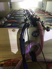
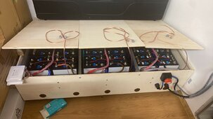
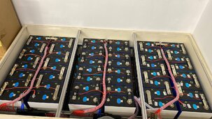
- 3x EVE LiFePo4 280ah battery banks 16s with JK BMS (already running for 2 years)
- 1x EVE LiFePo4 320ah battery bank 16s with JK BMS (in balancing as we speak)
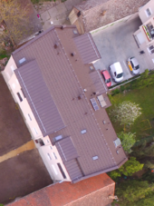
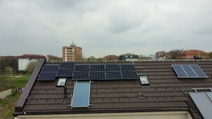
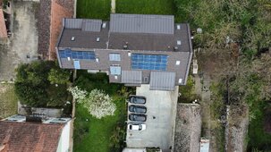
- 1x 18s 415W array (already running for 2 years)
- 1x 12s 460W array to be installed

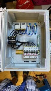
So now I’ve got my equipment and works are on. Photos will follow.

I’m not the guy throwing manuals to the bin and scraping data from forums but I got some good advice from @houseofancients @silverstone @uksa007 for which I’m thankful very much.

See you with comments and criticisms below, all is welcome to make this project better solution than initial one.
 

Attachments

  • IMG_0314.jpeg
    IMG_0314.jpeg
    160 KB · Views: 13
  • IMG_0320.jpeg
    IMG_0320.jpeg
    111.6 KB · Views: 12
  • IMG_0290.png
    IMG_0290.png
    1.6 MB · Views: 13
Now in middle of install I’ve found that grid and load lines should be threaded trough magnetic ring. I guess they meant ferrite rings

I’ve found only 2 in box with each inverter, one for DC battery cables and second for BMS communication.

Should I get additional rings?

Also, all rings are depicted to be inside box except for battery, that one should be outside inverter casing?
 
Present state photos
 

Attachments

  • 1662911878259999.jpeg
    1662911878259999.jpeg
    143.5 KB · Views: 15
  • 23652C04-AEF5-43CE-9F49-F8DC905A8838.jpeg
    23652C04-AEF5-43CE-9F49-F8DC905A8838.jpeg
    260.2 KB · Views: 14
  • IMG_1535.jpeg
    IMG_1535.jpeg
    431.4 KB · Views: 15
  • 1667236276295617.jpeg
    1667236276295617.jpeg
    105.7 KB · Views: 15
  • 167777075723849.jpeg
    167777075723849.jpeg
    225 KB · Views: 15
  • A7932162-5DE2-4ACC-9F0D-765474BB2E66.jpeg
    A7932162-5DE2-4ACC-9F0D-765474BB2E66.jpeg
    412.7 KB · Views: 14
  • dji_fly_20230408_103248_542_1680943429058_photo_optimized.jpeg
    dji_fly_20230408_103248_542_1680943429058_photo_optimized.jpeg
    332 KB · Views: 15
  • dji_fly_20230408_103846_549_1680943424359_photo_optimized.jpeg
    dji_fly_20230408_103846_549_1680943424359_photo_optimized.jpeg
    669 KB · Views: 14
  • dji_fly_20230423_180628_595_1682266819336_photo_optimized.jpeg
    dji_fly_20230423_180628_595_1682266819336_photo_optimized.jpeg
    753.4 KB · Views: 15
  • 783C7DB3-8CFB-4F90-933C-3106994C9A74.jpeg
    783C7DB3-8CFB-4F90-933C-3106994C9A74.jpeg
    193.7 KB · Views: 14
  • 166289473868398.jpeg
    166289473868398.jpeg
    239.8 KB · Views: 14
  • 42B8D131-781E-4AA2-94CA-BA3BAEF21F3A.jpeg
    42B8D131-781E-4AA2-94CA-BA3BAEF21F3A.jpeg
    198.3 KB · Views: 15
You can buy foldable ferrite rings with locking clips on f.ex. amazon.
As normal AC cables are often stiff and not very bendable to go through sealed ferrite rings multiple times.
The ones I mentioned are very easy to install and works well.
 
Been busy last few days bit here are results
 

Attachments

  • IMG_4337.jpeg
    IMG_4337.jpeg
    552.3 KB · Views: 12
  • IMG_4338.jpeg
    IMG_4338.jpeg
    464.8 KB · Views: 13
  • D03936D5-7E99-489D-813E-686CD95545DA.jpeg
    D03936D5-7E99-489D-813E-686CD95545DA.jpeg
    229.7 KB · Views: 15
  • DE2602E6-5E0F-455D-AFC7-1C63F56DE09F.jpeg
    DE2602E6-5E0F-455D-AFC7-1C63F56DE09F.jpeg
    137.8 KB · Views: 13
  • 19BA6374-D468-43EC-9CD4-14F186BB6A98.jpeg
    19BA6374-D468-43EC-9CD4-14F186BB6A98.jpeg
    395.2 KB · Views: 14
  • E5771286-DFF8-46E4-B3DD-9C388A225A9F.jpeg
    E5771286-DFF8-46E4-B3DD-9C388A225A9F.jpeg
    147.2 KB · Views: 11
  • F3B51637-E3DE-498B-8B2E-9008496B7805.jpeg
    F3B51637-E3DE-498B-8B2E-9008496B7805.jpeg
    113.8 KB · Views: 10
  • IMG_4354.jpeg
    IMG_4354.jpeg
    164.5 KB · Views: 10
  • IMG_4356.jpeg
    IMG_4356.jpeg
    180 KB · Views: 10
Now i have a question.

This afternoon i have tried system and it didn’t have enough solar so it was drawing from grid and not from batteries which were full.

Any setting that I’m not aware of to prevent this from happening?

My system is set to zero CT and all loads are on LOAD port.

When I disconnect grid physically everything works as it should.
If all of your loads are on the load port, you shouldn't have to set export to ct ( export to ct implies zero out the consumption on your grid.
You can set that for now to zero export to load ( the internal current sensors will be used)

Are your ct's connected, and the arrow pointing in the right direction ?
CT from both inverters are properly mounted and there is no flow to the grid. When batteries went to 100% production reduced.

What should I set to have inverters draw what loads need from solar and battery first and to switch to grid only if battery is empty?
 
CT from both inverters are properly mounted and there is no flow to the grid. When batteries went to 100% production reduced.

What should I set to have inverters draw what loads need from solar and battery first and to switch to grid only if battery is empty?
You have to use the TOU settings.
 
It does look like you are off to a good start, but a couple of observations and suggestions,

If I am wrong on any these no offense intended.

Doesn't appear the walls you mounted the inverters on are fireproof, like cement board. It appears to be just the sheetrock wall of a garage. If they are just sheetrock I would take the time to remount on cement board.

Doesn't look like the shelves are quite up to the weight even with all the supports
Looks like the shelves are particle board shelves with supports and ends or thin metal. DIY batteries must not sag even a few mm or over time there will be issues. This fire had some involvement with shelf collapse and making things worse.


It doesn't look like your battery end plates are enough to spread the load. General recomendation is 3/4 plywood slightly larger than the face of the battery and screws/wires with springs or muliple straps. But even with 3/4 it is recommended to reinforce with channel aluminum or equivalent.

In your case I would be worried that those shelves would ignite and ignite the vent hydrogen. You spent big bucks on the cells, good shelves aren't but a few hundred. If you can't stand on them and jump up and down they aren't good for this use.

@Will Prowse recommended some shelves in a recent video.

I didn't see mention of fuses at all - each bank should have its own class T and the busbar to the inverters should have a class T as well. If there is a cell short/vent without a class T betweeen strings all the others will start dumping current to the bad string. The house burned down was using Mega fuses which victron recommended, but the fire investigator pinned it as the ignition source. From the picture of the remains that one fuse holder is open and has melted plastic around it. Can't really tell for sure. But there have been tests posted where mega fuses were slammed with excess current and they exploded in a shower of sparks. The class T especially in the ignition protected mounts eliminate that possibility.


The below up-in-smoke article was a long chain of events, but the summary is:
There was a cell vent from an unknown cause. 50% of the gasses expepelled are pure hydrogen and a study show a vent fills a shipping container volume in 9 seconds. It also heats the cell to over 300c. At this point any little spark provides the ignition for the hydrogen and his house went up. From the records that were in the cloud it was about 20 minutes between the first sign of trouble and complete ignition. The family got out with just the clothes on their backs.


Here is the article:

Didn't see breakers/switches per bank for disconnecting each battery bank.

In any case make sure you have an ionizing smoke detector mounted nearby the batteries to give as early an alert as possible. And make sure it is tied to you home's smoke detector chain so they all go off.
 
Last edited:
One more tidbit - if you are grid-tie or need to pass inspection all of the wiring will need to be enclosed in metal raceway or conduit. AC wires one set and DC wire in a separate set. That is for all the battery wires and pv wires pretty much.

All the DC wiring must be in metal conduit if inside or attached to a structure. This is in case you get a short from critters chewing or in the case of pv wiring getting a hotspot in one conductor
 
Last edited:
It does look like you are off to a good start, but a couple of observations and suggestions,

If I am wrong on any these no offense intended.

Doesn't appear the walls you mounted the inverters on are fireproof, like cement board. It appears to be just the sheetrock wall of a garage. If they are just sheetrock I would take the time to remount on cement board.

Doesn't look like the shelves are quite up to the weight even with all the supports
Looks like the shelves are particle board shelves with supports and ends or thin metal. DIY batteries must not sag even a few mm or over time there will be issues. This fire had some involvement with shelf collapse and making things worse.


It doesn't look like your battery end plates are enough to spread the load. General recomendation is 3/4 plywood slightly larger than the face of the battery and screws/wires with springs or muliple straps. But even with 3/4 it is recommended to reinforce with channel aluminum or equivalent.

In your case I would be worried that those shelves would ignite and ignite the vent hydrogen. You spent big bucks on the cells, good shelves aren't but a few hundred. If you can't stand on them and jump up and down they aren't good for this use.

@Will Prowse recommended some shelves in a recent video.

I didn't see mention of fuses at all - each bank should have its own class T and the busbar to the inverters should have a class T as well. If there is a cell short/vent without a class T betweeen strings all the others will start dumping current to the bad string. The house burned down was using Mega fuses which victron recommended, but the fire investigator pinned it as the ignition source. From the picture of the remains that one fuse holder is open and has melted plastic around it. Can't really tell for sure. But there have been tests posted where mega fuses were slammed with excess current and they exploded in a shower of sparks. The class T especially in the ignition protected mounts eliminate that possibility.


The below up-in-smoke article was a long chain of events, but the summary is:
There was a cell vent from an unknown cause. 50% of the gasses expepelled are pure hydrogen and a study show a vent fills a shipping container volume in 9 seconds. It also heats the cell to over 300c. At this point any little spark provides the ignition for the hydrogen and his house went up. From the records that were in the cloud it was about 20 minutes between the first sign of trouble and complete ignition. The family got out with just the clothes on their backs.


Here is the article:

Didn't see breakers/switches per bank for disconnecting each battery bank.

In any case make sure you have an ionizing smoke detector mounted nearby the batteries to give as early an alert as possible. And make sure it is tied to you home's smoke detector chain so they all go off.

Still work in progress but I think i have got most of things done.

Wall where battery shelves are is reinforced concrete, it was a pain to drill all 36 holes in it. Should be strong enough as we used it as support climbing inverters up. They were more concern as one of them (right one) is on hollow blocks. For that I’ve used composite filler which worked surprisingly good.

On electrical part every bank has quick disconnect and fuse. Those are on sides, just didn’t got them on photos. Inverters have their own DC fuses in channel above. Code here doesn’t require metal casing for anything and rodents are rare and dealt with differently. Ultrasound devices around garage and most of the property.

Safety concerns are valid. I’ve been licensed firefighter for years. Smoke detectors are in the box and getting installed today latest. On top of temperature probes of each inverter and bms i have installed additional contact temperature probes on DC cables. There is 24/7 video surveillance on top.

Shelves are on my mind though. So far with 250mm between supports nothing moved but to be safe aluminum composite trays will get in once they arrive.

Any tips how to make inverters not draw from grid without throwing circuit breaker off?

Sorry, I write novels.

Dye makes the Sol-Ark inverters in the US and I would bet yours are equivalent to the 12k here.

Most Sol-Ark inverters of that style have a 'zero export' setting to let you leave the grid on and not send anything out to it.

Without digging into the manual, if you have grid connectors and load connectors you would connect the load screws to a critical loads panel and then the grid to grid. Then it would disconnect from the grid on power loss and not reconnect unless that model has CT clamps around the grid feed wires. The CT clamps serve to meassure power export but also to resync the frequency before coming back online.

The Sol-Ark 15k has a 200amp pass-through transfer switch and it eliminates the need for the CT clamps.

So poke through the manual and take a gander at those settings. ;)

I have a friend that lives in london so I throw in a bit of slang when talking to people from there. My wife is from Adelaide AU so we watch a ton of british TV. If you have any show recommendations holler and we will gander.

Are you 3 phase? I saw the three inverters side by side so it made me wonder.

An automatic transfer switch would be a good way, wire your inverter to the grid screws and the grid to the generator screws if you want to run off solar and flip back if solar is down.

If your DC/PV wires are anywhere that something they touch could catch fire you may want to think about it anyways.

On the shelves, I would hold up a long straight edge to the bottom of each shelf and verify no sagging. It might be an optical delusion, but seems like one might be.

For the hollow bricks I use a toggle bolt. Three inches long or more with a flip out piece that holds it in place without cracking or damaging the block. This style. So you just drill the hole and insert then it flips out inside and draws up flat against the back side. They make them to hold up to several hundred pounds.


Be careful with metal shelves - they are needed but they should be lined with something slick and inflammable. The batteries need to slide when they charge and discharge. And if the metal can of two batteries short to the shelf it can cause a short. This is out there but when I build my batteries at the new house I plan to line the overhead or each battery with rockwool. They make it in expanded for similar to fiberglass insulation that is flame proof and insulates very well.

On fuses, being in the UK you can use the NH1 style instead of class T. Basically each battery needs a fuse with a very high AIC on it. The NH1 similar to the class T is filled with sand to quench an arc if one starts. Your need this if you have a short in one string it keeps the others from making things worse.
I love novels, do them myself :)

I want to avoid transfer switch, inverter should do it by it self, just to explain to him to use whatever is in battery before drawing from grid.

All cables are silicone and with High temperature rating, but it’s a garage so flammables are there.

Have to dig deeper through manual but from my point of view all is done as it should. No energy is sent to grid but it draws from it on regular basis.
 
I love novels, do them myself :)

I want to avoid transfer switch, inverter should do it by it self, just to explain to him to use whatever is in battery before drawing from grid.

All cables are silicone and with High temperature rating, but it’s a garage so flammables are there.
So, hypothetically
6 strings of batteries 100amps each
One gets a short
now that single string starts to cook and vents a few cells.
and -
all 5 other strings are working properly and the are limited by their BMS
all 5 other strings dump 100amps each into the bad string.

So look at the time vs current curve on the fuses you used. Most fuses at 5x current will not blow until 10 seconds in.
In that 10 seconds the 500amps whacks the BMS and shorts the mosfets so the pack now has additional current to heat and more things in it vent.

But what happens to your silicon wires? It depends on the size wire, temperature rating of the wire, and length of the wire.

From calculations I've done with 2 meters of 2/0 and 4/0 welding wire rated 105c the sheath melts off in only a second or less. Then it goes on to hit 300c pretty quickly.

Now, increase the length and the resistance increases but so does the thermal mass. So the wire doesn't get as hot and there is air cooling unless in conduit. But keep the current up and in 10 seconds it is to hot to touch. Longer and the sheath will melt.

shorten the wire and the thermal mass and it will hit 500c in a second. But will be a curve...shorter than a foot and it just gets really hot.

this is why the recomendation is to fuse at the busbar end and if the wire is longer than 7 inches fuse at the other end. It is also why the recommend DC wires be in conduit, so the sheath melts and the fuse blows and the breaker trips. And any fire is contained.

and it is why you can't depend on the BMS as a protection device.


does any of that apply to your build?
Have to dig deeper through manual but from my point of view all is done as it should. No energy is sent to grid but it draws from it on regular basis.
This is what no-export means
 
Last edited:
Time of usage?

What should be set there?
 
Got it right today. Deye helpdesk was very efficient, they responded within minutes to my email.

Now I still have to get batteries communicate to inverters. For that I am still waiting on customs clearance of @uksa007 hardware. He jave sent them in time but customs are sooooo slow it is unbelievable.

Tomorrow I’ll tinker with RS485 / CAN port and connect everything via Solarasistant until hardware arrives. Now I charge and discharge based on voltage, very conservative.

Now one question for @houseofancients or whoever has an answer. I have placed 18 panels in series which give me 720 volts open circuit. When connected to inverter voltage drops to 520V. Is that normal or should I split my string to two of 9?

Is this happening under load ?
 
Last edited:
Back
Top