diy solar

diy solar

New no battery pure sine wave solar power system with smart switchers.

Thanks for ALL your work,
-will more 85 mfd 450v improve work ,ie motor start
-do you plan to use ISO on outside
Best
Yes 85 MFD is the minimum, I will leave to the user to manage capacitor size for motor starts Warning capacitor charge/discharge warnings must apply ⚠️
One Meg ohm resistors will bleed down capacitors over time.

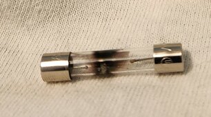
Just missing two 15Amp diodes to build one as soon as the new circuit boards arrive,
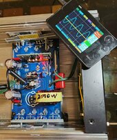
ISO transformer working just OK but additional improvements are needed to increase through put, it ran the small heater off the ISO transformer just fine.

Thank you for the starting information, still feel with improvement in the opto couplers drivers running the ISO transformers will be less of an issue in the future.

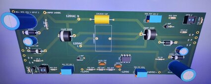
Right now a car battery could run the 555 60Hz signal for a month or more, 14 standard 12VDC solar panels will give you nice day time energy, charge battery systems for night time power and more 💚
Epoxy dip a working circuit board minus the heat sinks for ultimate weather proofing and out door durability.

More soon
 
Last edited:
Link to get new two FET inverter circuit board build files Gerber/Drill files in a zip file format.

Three dots file for download. Twofet.zip.


Two new FET working parts list May 8th 2024 Grid Works.

1 P channel Mosfet IXTK40P50P
1 N channel Mosfet 40N65
2 12 Volt zener diodes 5Watt
1 555 timer
2 15Amp diodes or 4 10Amp diodes
2 Flyback diodes 10 amp 200 volt rated
3 1Amp diodes
1 5.7K resistor
1 15K resistor
1 10K resistor
3 50K good qulity potenteometers
2 2A154k small green ceramic capacitors
2 optic couplers led input with Darrlington C/E output
3 820 ohm resistors
1 12VDC power supply must be isolated from earth ground/grid power
1 Inverter case with fan or heat sinks with fan
Each 140-160 VDC solar array needs 5Amp glass fast blow fuse and holder.
2 6K 5Watt resistors
2 10MFD 200volt capacitors
1 225J630 filter capacitor
1 60hz 2,000 watt choke
2 85 Mfd capacitors 450Volt
2 800ohm resistors
1 10-15 amp glass fast blow fuse and holder for Inverter output 120 VAC 60Hz.
END

More soon 😀
 

Attachments

  • 20240515_194731~2.jpg
    20240515_194731~2.jpg
    177.5 KB · Views: 7
Last edited:
Assembly tip use a large soldering iron to install pure copper wires to the circuitboard. Also use big iron to quickly solder in the big FETs and diodes. Put a small gap between the circuit board and the package of the 15Amp diodes when soldering in place think thermal and electrical isolation.

Use smaller iron with 555timer and the smaller parts.

Use isolation pads on the FETs, first test use dual 9VDC inputs and 12VDC on the 555timer circuit with a meter and oscilloscope you should be able to confirm basic operation and make safe changes if necessary.

Once you pass dual 21VDC input or higher the unit will likely run smooth at 140VDC solar inputs, Fuse everything with glass fuses.

I will make an instruction sheet after the first new circuit board build and testing.

More soon 😀
 
Last edited:
Don't fall for this solar scam, sales person tells customer to sign IPad so they can run their credit score.

After refusing the solar installation because of the $70,000.00 cost people with no solar panels on the roof years later find they are in collection and a lean has been filed on the home owners house. One lady discovered all this two years later when she went to sell the home and could not.

The company still claims with a lobby full of protesters that these customers are just suffering buyers remorse.

I can not believe the number of scams that occur every day against American consumers.

Just want you to know that solar inverters and panels simply do not cost that much. $70,000 is a whole lot of electricity and most still get an electric bill that is now 29% higher than just 4 years ago.

More soon
 
Last edited:
Real world report, at 5:00 PM yesterday the project system faulted and the lights went off.

The reason for the fault is simple attempting to run the mini split and more in the late afternoon after completely loosing sun conditions.In thirty minutes the system would have switched to grid power for the night. Going to re adjust the voltage controlled relays for better protection against this loss of solar.

Suspect one or more Mosfets have shorted source to drain and need replacing, Picture is of blown 10amp glass fuse from secondary ISO DC output from the diode bridge. This is the reason I say glass fuse everything.

More soon

Short has dissappear on main project inverter, Total carnage 2 40N65 MOSFETs shorted source to drain, one 10amp fuse in the secondary ISO transformer, restoration in progress.
 

Attachments

  • 20240519_110314~2.jpg
    20240519_110314~2.jpg
    139.6 KB · Views: 2
  • 20240519_124222~2.jpg
    20240519_124222~2.jpg
    76.5 KB · Views: 1
Last edited:
Main project inverter restored, now just have to put it back on the shelf.

About 3 hours so far working on it, more soon right here.

All in all a easy repair, needs a couple small adjustments on the voltage controlled relays and ready for summer ☀️

Project system fully functional again,💚
 

Attachments

  • 20240519_134716~2.jpg
    20240519_134716~2.jpg
    247.8 KB · Views: 1
  • 20240519_144621~2.jpg
    20240519_144621~2.jpg
    296.7 KB · Views: 1
Last edited:
Back
Top