Mine is 123456 from the factoryHello all,
Not really Solar related but mainly on the Daly BMS as i found the most info here.
I have the Daly 30/60A Smart BMS with the Bluetooth adapter and use the newer app "Smart BMS" from Daly.
Now i want to change some parameters but it requests an 6 number password.
I searched like crazy but found nothing.
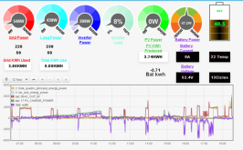
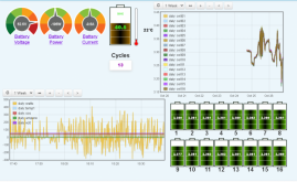
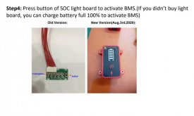
View attachment 21381View attachment 21382View attachment 21383
I hope anyone here has an idea since the response from Daly is crazy slow
Thanks!
You are using an out of date browser. It may not display this or other websites correctly.
You should upgrade or use an alternative browser.
You should upgrade or use an alternative browser.
New Daly "Smart" BMS w/ Communication. (80-250A)
- Thread starter Will Prowse
- Start date
tait97
New Member
Hello everyone
I'm using a Daly smart BMS with a logger created by Nuno Faria, (https://github.com/njfaria/dalylog) connected by RS485 to USB cable, and connected to Solpiplog by the same creator.
The software runs on a raspberry pi 4
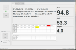

I'm using a Daly smart BMS with a logger created by Nuno Faria, (https://github.com/njfaria/dalylog) connected by RS485 to USB cable, and connected to Solpiplog by the same creator.
The software runs on a raspberry pi 4


Sverige
A Brit in Sweden
Helpful YouTube vid on how to successfully communicate with and configure the 4S Daly smart BMS.
Nb. When he says “Don’t buy it not from the official store” what he means is “only buy it from the Daly official store“
Nb. When he says “Don’t buy it not from the official store” what he means is “only buy it from the Daly official store“
tait97
New Member
when you order from Daly, please make sure you say that you want a "smart" BMSWould love to hear your thoughts on this: Click Here to see it on aliexpress (non affiliate link)
i ordered mine thinking i was getting a smart bluetooth BMS but got a normal one
and Daly says i will have to re-order smart bms if i want one
it is hard to understand what you are really getting
Sverige
A Brit in Sweden
I agree, the Daly range is kind of confusing and their website doesn’t help much. They would benefit from taking on a good distributor who could develop the documentation and marketing materials to better capture their rightful share of the English speaking market.when you order from Daly, please make sure you say that you want a "smart" BMS
i ordered mine thinking i was getting a smart bluetooth BMS but got a normal one
and Daly says i will have to re-order smart bms if i want one
it is hard to understand what you are really getting
tait97
New Member
Mine had to add at least 60cm.
And I have no problems.
And I have no problems.
Sverige
A Brit in Sweden
You mean the balancing cables to the battery? Normally these can be extended without causing problems, as they carry a relatively low current.I also own a Daly 16S 200A SmartBMS. A question about the 17p connectors / cables: The cables are a bit too short for me. Can I extend it twice? Or can lengthening it damage the BMS?
I have to say that I am now waiting for my second BMS from Daly in China, because my first suddenly after about 30 minutes just went dead. I had everything installed, connected and suddenly it went off without warning.
After that I discussed with the Chinese salesman for several days what it could have been.
In the end we agreed that I would get a new one at half the price.
In the short time it worked, I connected Bluetooth ,PC and this small display with capacitive touch and everything worked very well.
Why it no longer works could not be determined
@FilterGuy Can you provide details on how the Optocouplers are connected to each of the Victron bits? I understand how the BMS operates the optocouplers. I'm curious about where these are connected to the Victron bits, and what settings you used in each Victron unit to accomplish enabling and disabling charge and discharge. Victron's description of how to effect charge/charge disconnect with their Orion TR seems straightforward to me. Not so straightforward with their other devices. I'm hoping you can help.One thing I like to do with the Chargery is to use the relay signals to turn the loads and chargers on and off rather than try to use relays to directly cut the current. Even if you can only do this on the inverter, it can be a big improvement over trying to use a relay. Below is a design I did for someone that uses a Chargery BMS but no relays.
View attachment 24387
This was for a van conversion, so it is a bit more complicated than a stationary system where you don't have the DC loads or Alternator charging.
Thanks and Cheers,
Doug
So what’s the consensus on the Daly Smart BMS?
Can the you reliably pull data from the device and configure it to match your system?
I got mine yesterday (4s 60A), and yes, I can monitor and configure it via USB-UART (Using Sinowealth software) and the Android App. It took me about 2-3 hs of frustration and looking for the software getting the BT and USB working. It would have gone smoother if i had pre-installed it. On one laptop it connects every time (and has been running for the last 16 hrs straight logging) - on my other it can be pain to connect. I dont know why. Bluetooth has worked everytime ive connected it (30 times?).
The software has more control: ie it can set the cell high voltage protect, and the reconnect voltage separately in the software. In the app I can only set the high volt protect (when i do this it sets the h.voltage disconnect to that value, and the recconnect value to 0.1V less).
The app i can 'reboot' (system reset) the BMS - i dont know how to do that from the software. Only Zero drift current correction is available in the app, that and current calibration is in the software.
In the app it seems there is option to switch the charge and discharge on and off. That hasnt seemed to work - i need to test that with a higher current. I dont think the software has that option.
You can backup the software settings to a text file.... a snippet is below (BTW not my battery, but gives you an idea of the various parameters able to be set).
Oh, and i did test low temperature protection works.
Check out this link - the PDF was very helpful https://diysolarforum.com/threads/daly-smart-bms.9070/page-4#post-144059
Code:
[FlashData]

AFE Protect Config=76

AFE Over Voltage=4000

Pack Configuration=2B41

Voltage of Capacity 10%=2750

Voltage of Capacity 20%=2850

Voltage of Capacity 30%=2950

Voltage of Capacity 40%=3050

Voltage of Capacity 50%=3150

Voltage of Capacity 60%=3250

Voltage of Capacity 70%=3350

Voltage of Capacity 80%=3450

Voltage of Capacity 90%=3550

Voltage of Capacity 100%=3650

Design Capacity=280000

Full Charge Capacity=280000

Cycle Threshold=280000

Cycle Count=0

Learn Low Temperature=0.0

Near FCC=0

DfitterCur=500

PowerDownDelay=60

ChargeBackupDelay=1

ChargeBackupCurrent=200

RTCBackupDelay=5

Software Version=6.12

Hardware Version=1.10

Identify Device=00

Manufacturer Name=DALY--DALY

Manufacture Date=2019-06-14

Serial Number=0000

Device Name=SH39F003

Device Chemistry=LION

Battery Chemistry ID=002F

Over Voltage=3750

Over Voltage Release=3650

Over Voltage Delay=2

Over Voltage Release Delay=2

Charge End Voltage=3650

Charge End Current=200

Charge End Delay=5

Charge Over Current=300000

Charge Over Current Delay=2

Chg Over Curr Release Delay=1

Balance Voltage=3200

Balance Voltage Difference=50

Balance Open Current=30

Balance Open Delay=2

Charge Over Temperature=60.0

Charge Over Temp Release=55.0

Charge Under Temperature=-40.0

Charge Under Temp Release=-35.0

Temperature Protect Delay=1

Temperature Protect Release Delay=1

Under Voltage=2200

Under Voltage Release=2300

Under Voltage Delay=2

Under Voltage Release Delay=2

Discharge End Voltage=2200

Discharge End Delay=5

Discharge Over Current=-300000

Discharge Over Curren Delay=10

Discharge Over Curren2=-400000

Discharge Over Curren2 Delay=4

Detect Load Delay=4

Discharge PWM Frequency=4000

Slow Discharge Speed Ratio=30

Fast Discharge Speed Ratio=70

Discharge Over Temperature=70.0

Discharge Over Temp Release=65.0

Discharge Under Temperature=-40.0

Discharge Under Temp Release=-35.0

VPack Gain=2594

CADC Gain=-18

CADC Zero=1

Tempe1 Offset=0

Tempe2 Offset=0
Last edited:
Sverige
A Brit in Sweden
I found the pinout of the various connectors documented at this link
Is anyone good at translating Chinese? It would be good to know if the Chinese characters in this table contain any useful nuggets of info, to help us understand the interfaces on these BMS boards better:
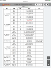
Is anyone good at translating Chinese? It would be good to know if the Chinese characters in this table contain any useful nuggets of info, to help us understand the interfaces on these BMS boards better:

Sverige
A Brit in Sweden
I’ve successfully connected to my new Daly smart BMS via Bluetooth today, and it took just a few mins to get connected because I had the right info from this and the other Daly threads on here. I’ll summarise what I did in the hope it helps someone else.
1) connect NTC thermistor to NTC port (BMS will not start without thermistor connected!)
2) connect B- lead on BMS to battery negative main terminal
3) connect Bluetooth dongle to UART connector
4) connect balance lead to battery (4S in my case) and before connecting it to BMS, verify with multimeter that balance lead is showing correct voltages (multimeter on 0-20V DC, negative lead on B- cable from BMS, then with positive multimeter lead, bottom pin on balance connector, black wire, reads 0V, second pin reads around 3.3V, third pin around 6.6V, fourth pin 9.9V, fifth pin 13.2V)
5) connect balance lead to BMS
6) use multimeter on continuity checker setting with positive lead on P- and negative lead on B-, multimeter reads open circuit, checked “Smart BMS“ app on iPhone, no Bluetooth device found
7) swapped multimeter cables, so positive lead on B-, negative lead on P-, multimeter shows zero ohms, BMS has now activated and “Smart BMS” app shows Bluetooth device available for connection.
Once connected via Bluetooth I found that I can view all the parameters shown in the screenshots and can set Cell high and low voltage disconnect by entering 123456 as password. Note: the SET button next to the text entry appears to always need to be pressed twice before the parameter gets written to the BMS, then there is a short delay of a few seconds before it updates in the app.
All testing was with the 4S LiFePO4 80A BMS part no R05A-FJ13
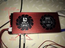
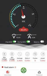
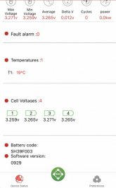
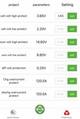
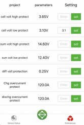


Last edited:
I’ve successfully connected to my new Daly smart BMS via Bluetooth today, and it took just a few mins to get connected because I had the right info from this and the other Daly threads on here. I’ll summarise what I did in the hope it helps someone else.
Good work, im glad some of the confusion around Daly SmartBMS is getting cleared up and others are having similar positive experinces. Yes, knowing the "123456" password helps and is neccessary to know.
Have you managed to get Charge and Discharge CMOS switching on/off to work? Ive been thinking of starting a blog to try to document my findings with this BMS and to collate information without having to read through 10's of pages of threads.
PS, I was once an Aussie in Sweden (Goteborg / Lund) many moons ago.
Sverige
A Brit in Sweden
You mean the slide “switches“ on the main page? No, those don’t allow control as far as I can see. Maybe a bad choice of icon to make them appear to be slide switches the user can interact with. I guess they are actually status indicators.Good work, im glad some of the confusion around Daly SmartBMS is getting cleared up and others are having similar positive experinces.
Have you managed to get Charge and Discharge CMOS switching on/off to work?
PS, I was once an Aussie in Sweden (Goteborg / Lund) many moons ago.
What caused you to go home from Sweden? Couldn’t take the smell of surströmmimg anymore?
Its curious, as when i slide the button, the password box shows up (as it does when trying to change a setting).You mean the slide “switches“ on the main page? No, those don’t allow control as far as I can see. Maybe a bad choice of icon to make them appear to be slide switches the user can interact with. I guess they are actually status indicators.
What caused you to go home from Sweden? Couldn’t take the smell of surströmmimg anymore?
Quality of life (and the weather!).
Sverige
A Brit in Sweden
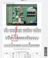
There is a useful document On the Daly website here which lists the pinout for the Multi pin connectors around the BMS board. Using google translate it’s possible to understand parts of the Chinese text, and the one which jumped out is the two pin J5 connector, shown in the below images.
The text in the table translates as “short pin 1 and pin 2 to activate BMS”.
I’ve tried this and it’s working on my 4S 80A unit, but it seems the short needs to be applied around 2 seconds as a brief momentary short doesn’t do the trick. I don’t know if applying a permanent short to these pins would keep the BMS active indefinitely, and I’m a little wary of trying this in case it could cause damage. If anyone who is trying to disable the sleep function on the BMS is brave enough to do this, let me know how it goes!
The 3 pin connector on my 4S BMS next to J5 seems to line up with the RLY pins on P1 in the wiring chart (to drive external relays?) and the other two pin connector (on the left in my photo) seems to align with VCC_ex and GND_ex in P1 (taking into account the spacing which misses a pin in P1). Would this be external power to drive an off board device? There‘s around 3V present on these pins when I meter them.
I’ve now fitted a momentary action push button switch on a short cable, wired into this J5 connector via a cut down RC model servo lead connector (cut down from 3 pins to 2 pins it will fit ok). Now I can press a button to wake the BMS when I want to connect via Bluetooth. Having the Bluetooth connection go back to sleep after the default 3600 seconds (one hour) is fine, as it will save battery power. If J5 can be held closed without causing any problems, then it would be possible to use a toggle switch and set the “sleep timer” via the mobile app to a very low number of seconds. Then you would have a two position switch for BMS on/off (presumably the off only works when the SCC is not charging the battery, as the charging will keep the BMS awake even with switch in off position).
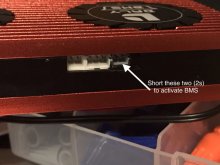
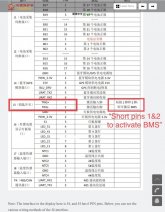


Last edited:
Similar threads
- Replies
- 7
- Views
- 1K
- Replies
- 25
- Views
- 3K
- Replies
- 251
- Views
- 21K
- Replies
- 16
- Views
- 3K


