diy solar

diy solar

Neat Electrical Panels

ArthurEld

Solar Wizard
Joined
Aug 3, 2020
Messages
2,289
Location
Palm Harbor, Florida
Guys, my main electrical panel wiring is a scary tangled up mess.

Since I am adding a Reliance transfer switch I will be adding a lot more wires and wire nuts.
It doesn't help that I have minimal electrical experience.
But, I am going to clean up the mess and I am going to add my new wires neatly.

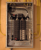
Here is one of the better examples I have found and there are many good examples.
I picked this one because it shows extra wire neatly coiled up and tucked away. I am hesitant to cut all of my transfer switch wires off but I probably just need to get over that and cut the wires.
My neutrals and grounds go to both sides. I guess it doesn't matter but it looks like crap.

Another thing that concerns me is that my main breaker is at the bottom. The wires for everything I want to do typically come in from the bottom.
But I am not sure if bringing in so many wires from the bottom is best.

I guess I am not the only one who thinks it should be neat and organized in there.

Please share any advice or links that are helpful

This is what I would like mine to look like
1612523029513.png
 
Last edited:
My OCD approves of all the straight lines!
I love that they numbered the sheathes.
If using staples like these guys, resist the urge to pound them in tight, you really don't want to crimp the insulation.

I don't like that the only two screws holding it to the plywood appear to be at the bottom are the sort that will cause the box to drop and fall off.
Doesn't look like the glands have cable clamps.
And of course, no 240V breakers.

Hopefully that level of pickiness won't scare you off posting photos of yours when done ;)
 
I love that they numbered the sheathes.
A little trick I learned from an electrician: cut a short piece of discarded Romex sheath, write the description/destination on it and slide it over the hot (black) wire before connecting it to the breaker.
I don't like that the only two screws holding it to the plywood appear to be at the bottom are the sort that will cause the box to drop and fall off.
I'm thinking that panel is mounted upside down.

I am a big fan of WAGO style connectors instead of wire nuts. Safer and easier to use.
I use those too, and they were very popular a few years back, but all of a sudden not displayed prominently, wire nuts are back in their place on the shelf. Have to look harder for the WAGO connectors, don't always find a full compliment in all sizes.
 
Thanks guys for the great suggestions. I noticed those screw holes looked upside down.
So the guy does beautiful wiring but mounts the panel upside down. lol I'm sure there's a reason.

I plan to add a before picture. It's not convenient to open to panel right now.
 
Orientation is usually due to feed, aerial feeds main breakers up, underground feed mains down. The neat coils are probably not dead, they look like GFI or arc fault breakers which have a tail. That install wouldn't pass up here, can't run wires through the main breaker compartment, there should be a divider.
yes-I like neat as well...
 
I don't like that the only two screws holding it to the plywood appear to be at the bottom are the sort that will cause the box to drop and fall off.

With that 2" conduit through plywood, don't think that's likely to happen.

Guys, my main electrical panel wiring is a scary tangled up mess.

I am hesitant to cut all of my transfer switch wires off but I probably just need to get over that and cut the wires.

I like to keep all the "service loop" I can, because I keep returning and making it different.
1) Can you pull the transfer switch wires back into the transfer switch, keep extra length out of main panel?
2) With wall opened up, how about pulling lengths of romex back into wall cavity?
3) Re-route some romex so it goes straight to transfer switch? But neutral presently bypasses it.

Wires are supposed to be secured within some short distance of the box.
Sometimes I put romex clamps on a box so the clamp is outside and nut inside. But done the other way with screw clamp on the inside, you could stuff the (still sheathed) romex back into wall cavity reducing what's in the box.

The picture you show has neatly coiled pigtails for GFCI neutral. That was possible because neutral bars are along side the breakers, which mine aren't.
Another type now available is "plug on neutral". A plug-on (no screws) rail is under the breakers, and GFCI/AFCI breakers for this have no pigtail, rather just plug on to the rail.

Hmm! I just realized an issue with the 120% rule for adding PV breakers. If I have a 100A panel and main breaker with 20A PV breaker, and loads are completely unbalanced with 120A of 120V all on one phase, the hot busbar isn't a problem because it carries 100A from one end and 20A fro m the other. But, if all breakers were GFCI/AFCI with plug-on neutral, it would have 120A in the neutral.

I guess flying wire neutral has the same issue. The 120A of circuits could all have their neutrals returning through one neutral busbar on one side of the panel.
 
For mobile installations, is there anything better than the usual panels?
 
The discarded romex sheath is a great thing to do. We use it a lot and makes identification easy.
 
Is there no way to delete my own post? Realized others already made my observation. No sense in 15 echos.
 
Hedges, that is a great idea to push the extra wire into the transfer switch. I am concerned that I might decide to move the transfer switch or that the permit inspector might make me move it. It's often better to leave options open.
My panel is on a cinder block wall so no wires going into the wall. They do go through a channel to the ceiling.

I am going to wait until I post a picture to ask more questions
 
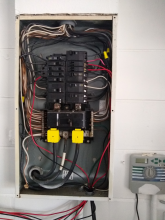
Ok, here is my panel. It actually isn't as bad as I remembered it.
But you can see the wires I added from the bottom aren't looking very neat and I have to add about 20 more.
At least 7 more wire nuts too.

This is a temporary setup. I will be using conduit for the permanent setup.

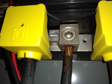
The picture shows the new yellow covers I added over the main lugs and wires coming in.
And it shows the channel going up toward the ceiling.

I don't know if I should separate the neutrals and grounds. Some are on the opposite side of the wires they belong with.
1612620987683.png
 
Looks to me like there's plenty of space to coil up the extra length at the bottom of box.
A coil is some inductance, although "air core" and 60 Hz isn't a big deal. If neutral was together with hot when coiled it wouldn't matter at all, but that's now how your transfer switch wiring works.

Having hot split from neutral and routed separately through a different hole in the steel box may or may not add more inductance than a coil of wire in air.
To the extent a hot circuit comes from main breaker panel, exits through conduit, goes through transfer switch and back through same conduit, no inductance to speak of.
If a hot circuit goes from main panel to inverter through one path, then back through transfer switch and conduit by a different path, the area of the loop formed creates inductance. If the loop wraps around a piece of steel, more inductance.

Doesn't matter if neutral and ground go to busbars on opposite side of box. The area of any (magnetic) loop in air within the dimensions of a box seems to be of no concern. Especially for ground, which carries fault currents. (Circuits carrying harmonics, like of a switcher or power supply front end with poor PF, would emit more EMI given a loop between hot and neutral.)

I suppose there's a box bonding screw on the neutral?
I don't see a wire from a grounding rod. I would expect that to connect to a box which has neutral and ground tied together.
 
Looks to me like there's plenty of space to coil up the extra length at the bottom of box.
A coil is some inductance, although "air core" and 60 Hz isn't a big deal. If neutral was together with hot when coiled it wouldn't matter at all, but that's now how your transfer switch wiring works.

Having hot split from neutral and routed separately through a different hole in the steel box may or may not add more inductance than a coil of wire in air.
To the extent a hot circuit comes from main breaker panel, exits through conduit, goes through transfer switch and back through same conduit, no inductance to speak of.
If a hot circuit goes from main panel to inverter through one path, then back through transfer switch and conduit by a different path, the area of the loop formed creates inductance. If the loop wraps around a piece of steel, more inductance.

Doesn't matter if neutral and ground go to busbars on opposite side of box. The area of any (magnetic) loop in air within the dimensions of a box seems to be of no concern. Especially for ground, which carries fault currents. (Circuits carrying harmonics, like of a switcher or power supply front end with poor PF, would emit more EMI given a loop between hot and neutral.)
I assume that the wires running from the main panel to the transfer switch then back to the main panel don't need neutral.
And the wires from the Solark to the transfer switch don't need a neutral.
But the wires from the main panel to the Solark do need neutral. I am wondering if that neutral should be thicker than the rest of the wires.

It would be possible to run a neutral wire from the main panel into the transfer switch then out through the conduit to the Solark.
But the Solark manual doesn't think that is necessary.
I suppose there's a box bonding screw on the neutral?
I don't see a wire from a grounding rod. I would expect that to connect to a box which has neutral and ground tied together.
I assume the big cable between the two main hot cables is the ground. I don't know how the bonding works. I will try to see if I can figure it out when I am in there again.
 
I assume the big cable between the two main hot cables is the ground. I don't know how the bonding works. I will try to see if I can figure it out when I am in there again.

The big cable with white tape is the neutral. When a 120V load is powered (and assuming there isn't a balancing 120V load on the other hot phase), its return current run through neutral back to the grid.

We do not use a length of wire both to carry neutral currents and to carry any ground currents. We use a single connection between neutral and ground. (except, for the length of the busbar in the panel where bonding occurs, we do let the busbar carry both.)

I expect to see either:

A separate ground busbar, with only green or bare wires connected, fed by a fat ground wire. And neutral with all white wires.

Or, busbar with both bare ground wires and white neutral wires, and a fat wire going to ground rod. This busbar would connect to box, typically with a green screw. This configuration includes or is right at meter/utility entrance.
 
I assume that the wires running from the main panel to the transfer switch then back to the main panel don't need neutral.
And the wires from the Solark to the transfer switch don't need a neutral.
But the wires from the main panel to the Solark do need neutral. I am wondering if that neutral should be thicker than the rest of the wires.

It would be possible to run a neutral wire from the main panel into the transfer switch then out through the conduit to the Solark.
But the Solark manual doesn't think that is necessary.

Ideally the currents flowing in a cable or conduit sum to zero. Total flowing one direction equals total flowing other direction, no magnetic field created, no impedance due to inductance, no transformer-type coupling from one circuit to another. No E-field between this group of wires and another group routed elsewhere.

I've heard of ferrous components getting hot when wires formed a coil by going one direction on one side, other direction on the other side. But my bench measurements didn't detect any impedance. Electric and magnetic field between separate runs would expose occupants to ELF, while having current and its return adjacent virtually eliminates that.

Hot from panel to transfer switch, if it carries current, has equal and opposite current back from transfer switch to panel cancel each other, so no magnetic field created. They are of the same potential so they have an electric field. If metallic conduit or if there is a ground wire, that captures the electric field and carries a small current depending on capacitance.

Hot from panel to Solark in one conduit (which has neutral), then from Solark to transfer switch (without neutral) and from transfer switch back to panel forms a loop of current that encloses area. That is a loop antenna, creates a magnetic field. It attempts to induce an equal and opposite in the (resistive) metallic conduit, assuming a closed electrical loop is formed by the conduit.

(There's the mistake I made in my experiment - I made an inductor subject to eddy currents, but didn't make a ferrous winding around my "transformer", which would have gotten hot. I should repeat that, measure voltage open circuit and current short circuit in the conduit.)

If your transfer switch had conduit large enough, hot and neutral from panel to Solark could have gone through transfer switch, also hot back from Solark to transfer switch. A second (same size) neutral from Solark back through transfer switch to panel, forming a loop, would also serve to carry return currents.

I don't know the magnitude of the problem from not providing a neutral to carry return currents. You could do an experiment by running a loop of 12 awg. (maybe repurpose one of the existing wires from transfer switch if you can't pull another; just add wire through Solark back to breaker panel to complete the loop.) It doesn't even need to connect to neutral busbar. Measure open circuit voltage. Measure short-circuit current. With flying wires and now conduit as in your photo, this will show the full current available. Once conduit makes a complete loop, and electrical circuit, that will carry some of that current and heat up according to I^2R.

The total power which can be transferred from your intended circuit to this loop of wire or the conduit is limited by the amount of magnetic coupling.
 
The big cable with white tape is the neutral. When a 120V load is powered (and assuming there isn't a balancing 120V load on the other hot phase), its return current run through neutral back to the grid.

We do not use a length of wire both to carry neutral currents and to carry any ground currents. We use a single connection between neutral and ground. (except, for the length of the busbar in the panel where bonding occurs, we do let the busbar carry both.)

I expect to see either:

A separate ground busbar, with only green or bare wires connected, fed by a fat ground wire. And neutral with all white wires.

Or, busbar with both bare ground wires and white neutral wires, and a fat wire going to ground rod. This busbar would connect to box, typically with a green screw. This configuration includes or is right at meter/utility entrance.
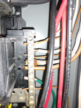
I don't see a green screw.
The ground bar, the neutral bar and the neutral cable are all tied together.

There are a couple of fat wires going to the ground bar
1613836373715.png
There is a lug next to neutral but nothing is attached
1613837222779.png
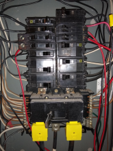
Here is a close up of the panel
1613837358382.png
 
The fat wires to neutral bar could include one for a ground rod, or could be associated with a branch circuit of similarly fat wires.
The stranded aluminum wire is a particular candidate. Lug next to neutral would have been a typical place to connect.
Are you aware of a ground rod outside?

I think for service using awg 1 through 3/0 conductors, ground conductor is to be awg 6 to 4 (copper), awg 4 to 2 (aluminum)

The box should be electrically connected to the ground/neutral bar. You can check that with a DMM, but because there is conduit going to circuits it is possible only that circuit provides the bonding. Look again for a bonding screw (they've always been green when I've seen them.) To check electrically, could turn off the circuit which is routed through metal conduit, disconnect its ground wire, then check box to neutral with DMM.
 
It looks like the incoming neutral is connected to a bar tying both neutral buss bars. All of the grounds are connected to the same buss bars as the neutral. There are no ground buss bars as is normal practice in some jurisdictions.
 
Back
Top