Hedges
I See Electromagnetic Fields!
- Joined
- Mar 28, 2020
- Messages
- 20,632
Extension cord of suitable gauge is good up to 1800 watts. If inverter has multiple AC outlets, better two use two cords; the typical plug/socket is meant for up to 15A but circuits up to 20A so two loads on one duplex outlet. (I don't know your inverter's output)
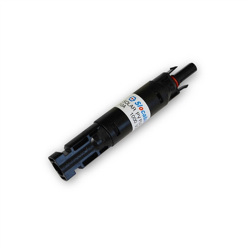
Some ME connectors are rated for more current. If you want 8 awg try to find wires and "Y" of that size. Most MC connectors rated 30A (less if smaller than 10 awg), but a few are rated for more. You're supposed to size the wire for 1.56x Isc x number of parallel PV panels or strings. You can also convert from MC to another type of wire, usually in a box followed by conduit.
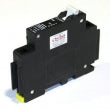
If you have fuse per PV string, probably no need for additional fuse on combined wire. But a breaker or switch of suitable rating is good as disconnect.
Your location may not have yet adopted code requiring RSD. If it does, I think it applies if wires from ground mount panels enter the house, except if all in conduit it does not.
With your panels configured 3s4p, I think a mechanical PV disconnect switch I saw somewhere around here could meet the need. RSD is supposed to isolate panels so voltage between any two wires is < 80V, also some wattage limit. Just a 4PST switch the the disconnect I saw might do that for you. At least if those are 100W panels so only 300W per string. That would be cheaper and simpler than an electronic RSD box per panel.
Even with RSD, you could string 3, 100W panels in series into its connectors. I saw one 4-panel RSD with ratings such that it should support a dozen of my 12V 120 panels. In my case I would have 4x 3s combined into 12s so that works. Not sure your 4x 3s could combine to 3s4p with one quad RSD; you might need four individual RSD.
Some ME connectors are rated for more current. If you want 8 awg try to find wires and "Y" of that size. Most MC connectors rated 30A (less if smaller than 10 awg), but a few are rated for more. You're supposed to size the wire for 1.56x Isc x number of parallel PV panels or strings. You can also convert from MC to another type of wire, usually in a box followed by conduit.
If you have fuse per PV string, probably no need for additional fuse on combined wire. But a breaker or switch of suitable rating is good as disconnect.
Your location may not have yet adopted code requiring RSD. If it does, I think it applies if wires from ground mount panels enter the house, except if all in conduit it does not.
With your panels configured 3s4p, I think a mechanical PV disconnect switch I saw somewhere around here could meet the need. RSD is supposed to isolate panels so voltage between any two wires is < 80V, also some wattage limit. Just a 4PST switch the the disconnect I saw might do that for you. At least if those are 100W panels so only 300W per string. That would be cheaper and simpler than an electronic RSD box per panel.
Even with RSD, you could string 3, 100W panels in series into its connectors. I saw one 4-panel RSD with ratings such that it should support a dozen of my 12V 120 panels. In my case I would have 4x 3s combined into 12s so that works. Not sure your 4x 3s could combine to 3s4p with one quad RSD; you might need four individual RSD.
")