


You are using an out of date browser. It may not display this or other websites correctly.
You should upgrade or use an alternative browser.
You should upgrade or use an alternative browser.
RVs with DIY Lithium
- Thread starter Txglader
- Start date
MrM1
I'm Here, But I'm Not All There
Thanks. Glad I found this info. I am going to do something for sureI linked some available on amazon from my site. Parts express carries them as well.
DerpsyDoodler
Solar Addict
- Joined
- Jan 10, 2021
- Messages
- 2,247
Perhaps dove tailing would also be useful?Most of the cabinetry in my RV is MDF. Yes, it does not hold up. But it takes a few years. If you glued everything together and didn't use fasteners (screws) it might not be so bad.
Hi folks, TxGlader thanks for telling me about this RV-centric discussion. I am an RV'er looking to go from wet cell to LiFePo4 tech and in the debating phase between drop in vs DIY. Obviously I am leaning to DIY, in part because I want to be able to understand what is going on if there is an issue and partly because I am cheap and DIY can afford much more capacity for the same of less expenditure.
In reading about LFP batteries I have seen repeatedly that they should not be held at full charge "for long periods". LFP like to be cycled. For folks that are full time and using solar that is not an issues as the batteries are constantly being charged and discharged. For part-timers and those that spend much time with shore powers it is conceivable that the batteries could go weeks or even months with minimal discharge. This poses several questions:
1) At what SOC is it safe to store your LFP batteries?
2) Since there is a small range in voltage change between is it better to use amperage as a measure?
3) If you fit the part-time scenario would you set your max charge for 100 AHr at say 90 amps to avoid storing your rig at full charge?
The best way to measure SoC is through measurement of amperage flow via a shunt monitor. There are a few options for that - I like the victron gear (but it is a bit pricy, but works really nicely) but there are cheaper options.
The best bang for the buck IMO is a victron smart shunt. $130 gives you a Bluetooth app interface AND you can integrate it online for stats.
Once you’ve established reasonable voltage ranges for your SoC, you can use them as a bit of a cheat sheet. I’m going to be using voltage as the definition for my controller, which is going to enforce various use modes. I’m writing the code now, but am looking at something like 75-80% charge for storage mode.
One key idea to explore: what’s the definition of storage? In my camper, I’m running a dometic 12v cooler/freezer and a couple of raspberry pi’s. One for victron monitoring and one for 4g internet access. That means that I always support a smallish set of loads. That keeps my battery exercised a bit.
Pure storage means - disconnecting the pack from all loads and charging. For that my impression is like 60% SoC is about ideal.
Hmm, in fact, that gives me an idea for a charge management mode - something like storage/excercise mode. I could call it Prius mode. Those cars like to charge their packs to a mere 80% for maximum life.
(It’s a very Toyota mentality. They are crazy about reliability.)
Ordered these from China, you can find locally so not to have to wait.
I’ve always used these:
2 day delivery with prime
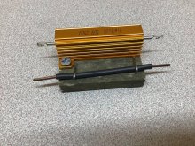

How are you compressing the cells?
TexasFan
New Member
- Joined
- Mar 4, 2021
- Messages
- 48
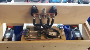
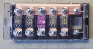
I am also building 4 272 to be paralleled. I was just going to wire them from one battery to the next. I see you are combining them on a bus bar which I believe achieves the same objective 4 12V 272AH = 12V 1088AH or is method preferred? or safer? I will run fuses between each battery.Battery box 2.0. I found out that MDF will not hold up th the vibrations in an RV so I went with plywood. The board that the bus bar is on is temporary. Need to get all the cells in it now and install the positive leads. Also balancing leads.
View attachment 41949
I am not sure if one way is better than the other. Each battery positive will connect to one of the 100A fuses. The 400A will go to a disconnect switch. The switch is connected to a Victron Power In.I am also building 4 272 to be paralleled. I was just going to wire them from one battery to the next. I see you are combining them on a bus bar which I believe achieves the same objective 4 12V 272AH = 12V 1088AH or is method preferred? or safer? I will run fuses between each battery.
Attachments
I remove one end of the box and put all the cells in. I use a clamp to compress a little and allow me to put the screws back in the end of the box.How are you compressing the cells?
corporate.joe
Solar Enthusiast
- Joined
- Jan 25, 2021
- Messages
- 174
I'm following your build very closely. I'm building a bank of 3 24v batteries and I'm very curious how your bank of 4 turns out. Individual fuse for each battery and then one larger fuse/breaker after they join sounds like good practice to me.
I'm rolling through ideas on how to make my packs modular because I plan to separate them. One or two of them may be moved to an RV install.
Is this for a fifth wheel, TT, or motor home?
I'm rolling through ideas on how to make my packs modular because I plan to separate them. One or two of them may be moved to an RV install.
Is this for a fifth wheel, TT, or motor home?
My original plan was to make them modular. Changed my mind to make the fit under the stairs.I'm following your build very closely. I'm building a bank of 3 24v batteries and I'm very curious how your bank of 4 turns out. Individual fuse for each battery and then one larger fuse/breaker after they join sounds like good practice to me.
I'm rolling through ideas on how to make my packs modular because I plan to separate them. One or two of them may be moved to an RV install.
Is this for a fifth wheel, TT, or motor home?
This is going in a 2019 Grand Design Reflection 295RL 150 series.
SO this is 16 cells and 4 BMS in one box? Just confirming what appears in the photo.Battery box 2.0. I found out that MDF will not hold up th the vibrations in an RV so I went with plywood. The board that the bus bar is on is temporary. Need to get all the cells in it now and install the positive leads. Also balancing leads.
View attachment 41949
SO when you are connected to shore power but use the lights, or run other small 12v parasitic loads that is sufficient to "exercise" the batteries when the rig is, as an example, parked at a RV park or in your derive way. On the other hand, if you are storing for the season (several months on no use), drop the SOC to about 60% and disconnect the battery bank. Do I have this correct?The best way to measure SoC is through measurement of amperage flow via a shunt monitor. There are a few options for that - I like the victron gear (but it is a bit pricy, but works really nicely) but there are cheaper options.
The best bang for the buck IMO is a victron smart shunt. $130 gives you a Bluetooth app interface AND you can integrate it online for stats.
Once you’ve established reasonable voltage ranges for your SoC, you can use them as a bit of a cheat sheet. I’m going to be using voltage as the definition for my controller, which is going to enforce various use modes. I’m writing the code now, but am looking at something like 75-80% charge for storage mode.
One key idea to explore: what’s the definition of storage? In my camper, I’m running a dometic 12v cooler/freezer and a couple of raspberry pi’s. One for victron monitoring and one for 4g internet access. That means that I always support a smallish set of loads. That keeps my battery exercised a bit.
Pure storage means - disconnecting the pack from all loads and charging. For that my impression is like 60% SoC is about ideal.
Hmm, in fact, that gives me an idea for a charge management mode - something like storage/excercise mode. I could call it Prius mode. Those cars like to charge their packs to a mere 80% for maximum life.
(It’s a very Toyota mentality. They are crazy about reliability.)
On a seperate note I am also very interested in how you use the Pi units to monitor Victron and provide 4G. I would not want to drag that conversation into this post but If you are interested in sharing please PM me.
Here, I kicked this off just for you.

 diysolarforum.com
RPi Internet and Victron Monitoring
Got a request for info, so I figured I'd bring this over here. I use a bunch of victron bits in my RV now and have added a raspberry pi running the victron venus image and I have a second pi that rocks a 4g card to provide internets. First up, the Internet Pi: This is a Pi 3+ that has a sixfab...
diysolarforum.com
You are correct on the configuration and that you should store at 60% if for long term storage.SO this is 16 cells and 4 BMS in one box? Just confirming what appears in the photo.
SO when you are connected to shore power but use the lights, or run other small 12v parasitic loads that is sufficient to "exercise" the batteries when the rig is, as an example, parked at a RV park or in your derive way. On the other hand, if you are storing for the season (several months on no use), drop the SOC to about 60% and disconnect the battery bank. Do I have this correct?
On a seperate note I am also very interested in how you use the Pi units to monitor Victron and provide 4G. I would not want to drag that conversation into this post but If you are interested in sharing please PM me.
I have the Cerbo GX with the touch color display to monitor with. The PI sounds like a great alternative but I don't know much about them. I am fine with discussing them in this thread if someone has the knowledge to jump in.
I am using a Victron 3000 Inverter/Charger. If I am connected to shore power then the converter should be supplying DC power. Am I thinking correctly that in this senerio, I will not need to precharge when connecting the battery bank?Ordered these from China, you can find locally so not to have to wait.
View attachment 41761
I am using a Victron 3000 Inverter/Charger. If I am connected to shore power then the converter should be supplying DC power. Am I thinking correctly that in this senerio, I will not need to precharge when connecting the battery bank?
Hmm, that's an interesting question. I'm not qualified to answer it but it did get me to thinking. It comes down to if the capacitors are charged only from the battery side or if they get charged from any charge (i.e. the built-in charger). Also, would you connect the inverter to shore power without it already being connected to battery?
TexasFan
New Member
- Joined
- Mar 4, 2021
- Messages
- 48
I don't what brand my rig came with but it is also a 3000w inverter/charger and mine does charge up the batteries when I am plugged in. There should settings on the Inverter/Charger to set type of battery so it will charge it correctly.I am using a Victron 3000 Inverter/Charger. If I am connected to shore power then the converter should be supplying DC power. Am I thinking correctly that in this senerio, I will not need to precharge when connecting the battery bank?
Similar threads
- Replies
- 10
- Views
- 457
- Replies
- 85
- Views
- 4K
- Replies
- 13
- Views
- 379
- Replies
- 14
- Views
- 437