Thanks, that's basically the other option I considered, but I thought my electrical engineering skills too weak at this point to determine how it would behave in a fully charged state. You provided me with some ammunition to investigate that further. What made you decide against an MPPT converter?I looked at using an MPPT converter to charge a 12V battery from a 48V battery, but I ended up getting a voltage & current limited DC-DC converter and it works well. I have a diode on the output to prevent backwards current from the 12V battery when the DC-DC converter is in standby, though I'm not entirely sure I need it, but for now this is the safe option. It charges in constant current mode up to the set current, then when it reaches the set voltage, it switches over to constant voltage mode. I believe you could operate 2 or more in parallel if you wanted a faster charge rate (I recommend diodes for each). I also have a boost converter from the same manufacturer to charge the 48V from the 12V and that works for the rare occasions where I want that. The diode is critical in this direction though.


You are using an out of date browser. It may not display this or other websites correctly.
You should upgrade or use an alternative browser.
You should upgrade or use an alternative browser.
Sailboat conversion from 14 hp Diesel to 10 Kw 48V electric motor
- Thread starter keimor85
- Start date
I couldn't find enough data on the MPPT converters I looked at to determine what they would do when connected to an input without the limits of solar panels. A battery on the solar input is somewhat equivalent to a fixed voltage unlimited current solar panel. The MPPT would need some sort of current limiting feature so as to not destroy itself - I imagine some do this, but I couldn't find this out without testing, possibly to destruction. I also wasn't sure how the MPPT algorithm would work with a battery since the battery would control the voltage rather than the MPPT. I decided to go with something that had a known and controllable limits. Before finding the current limited DC-DC converter, I even wondered about using a motor controller to perform current limiting. After I found a whole lot of youtube videos on this and other DC-DC converters, I went ahead with my purchase. Although my battery banks are still on the test bench not in use on my boat yet, the chargers work as advertised and I'm very happy. The diode reduces the efficiency to about 80% and I've looked at MOSFET 'ideal diodes' to remove that source of loss, but not had success with those yet. I run the DC-DC converter below its maximum to keep the heat down and the efficiency as high as I can. I find it charges fast enough for my needs. I need to re-mount the converter in a sealed aluminum box that would also act as a heat sink to protect it from the marine environment.Thanks, that's basically the other option I considered, but I thought my electrical engineering skills too weak at this point to determine how it would behave in a fully charged state. You provided me with some ammunition to investigate that further. What made you decide against an MPPT converter?
Keep in mind the DC-DC converter I linked is not isolated, care must be taken to ensure that the DC-DC converter is the only connection between the two battery banks. Fuses at both ends of each battery are wise. I've even got a fuse in the middle of the 48V battery.
You also need to set the voltage limit higher to compensate for the diode, this is a bit of a bummer as it would be nice to dial in the final voltage directly - I've found the DC-DC converter to be quite accurate. I've only gone up to fully charged while watching and adjusting the voltage as required, though the current does drop to zero when the set voltage is reached. I will set a lower voltage to be safe if unattended since I'm using lithium batteries and there is no harm in not fully charging them apart from the minor loss of capacity. Once happy with a particular voltage & current limit, the DC-DC converter can save this for next time. BMS high voltage cut out would offer a second line of defence.
Last edited:
Thank you. I see I'm going to need to learn a whole lot more about electronics to make this call correctly.The MPPT would need some sort of current limiting feature so as to not destroy itself...
Here is a open source mppt controller that claims overcurrent protection, with schematics. I wonder what they mean by overcurrent protection, blow a fuse? Or does it do limiting. Maybe I can eventually read that schematic and find out.
MisterSandals
Participation Medalist
Its actually a fairly common feature of some SCC's. You simply enter a value for the max charging amps and you're done. You just need to make sure you buy an SCC with that ability if you need that functionality.I see I'm going to need to learn a whole lot more about electronics to make this call correctly.
I have a Victron 100/30 and can set it with a bluetooth app in about 15 seconds.
Does that value specifically refer to output charging current? I would expect that limiting output current automatically limits input current for these buck converter-type devices, that just seems to make sense. But I'm not an ee...Its actually a fairly common feature of some SCC's. You simply enter a value for the max charging amps and you're done. You just need to make sure you buy an SCC with that ability if you need that functionality.
I have a Victron 100/30 and can set it with a bluetooth app in about 15 seconds.
MisterSandals
Participation Medalist
Yes, its as simple as that.Does that value specifically refer to output charging current?
When my RV batteries (LiFePO4) are in storage mode, i still have to charge gently from time to time. I have a separate port BMS that allows only 8amps charge current. So i turn the BMS charging current down to 6amps while i get my cells back up to around 3.25v.
I have a far more expensive Morningstar Tristar MPPT45 (11 years old now) that does not have current limiting (well if it does i need to program it with a PC and a serial cable... so that's out). Maybe the newer ones support it, I think its a good feature.
I have ordered a Sevcon 48V to12V DC to DC converter kit. I don't think the diode is needed but I'll check into it. Thanks for the heads up on the diode.I looked at using an MPPT converter to charge a 12V battery from a 48V battery, but I ended up getting a voltage & current limited DC-DC converter and it works well. I have a diode on the output to prevent backwards current from the 12V battery when the DC-DC converter is in standby, though I'm not entirely sure I need it, but for now this is the safe option. It charges in constant current mode up to the set current, then when it reaches the set voltage, it switches over to constant voltage mode. I believe you could operate 2 or more in parallel if you wanted a faster charge rate (I recommend diodes for each). I also have a boost converter from the same manufacturer to charge the 48V from the 12V and that works for the rare occasions where I want that. The diode is critical in this direction though.
I agree. For a number of MPPTs and other DC-DC converters, I couldn't tell from the product brochures what they would do at their limits - would they cut out, or hold at the limit? That's why I ended up going with DC-DC converters that advertised constant current / constant voltage behaviour. The youtube videos showed me real life experiences confirming the advertisements and my own experience has matched. At least open source with schematics you've got a chance of working this out for yourself - sorry, but I'll have to leave that to you as I don't have the time.Thank you. I see I'm going to need to learn a whole lot more about electronics to make this call correctly.
Here is a open source mppt controller that claims overcurrent protection, with schematics. I wonder what they mean by overcurrent protection, blow a fuse? Or does it do limiting. Maybe I can eventually read that schematic and find out.
I'm not familiar with them, so sorry, I have no advice to offer, but good luck! In my circumstance, the diode protects the DC-DC converter itself when in standby or off, i.e. not in normal operation, so make sure you consider the other possible conditions.I have ordered a Sevcon 48V to12V DC to DC converter kit. I don't think the diode is needed but I'll check into it. Thanks for the heads up on the diode.
What make of diesel engine. Universal?I have been there for several years. My diesel was sill running very well with the exception that I was starting to get raw water into the oil last summer. I eliminated all of the simple root causes and finally determined that the water jacket must have finally started to rust through. So I changed the oil every month until I hauled out in early Nov and made the decision to go electric. I'm starting to strip the boat of all diesel gear.
It is/was a Volvo Penta MD7A 2 cylinder 14.3 HP. I removed it from the engine bay this week. My new 10KW electric motor assembly arrived today. Still wailing on the battery cells (16 3.2V LiFeO4) and BMS. Both are coming from China. I will start the motor install next week.What make of diesel engine. Universal?
Attachments
My Daly 16S 300A 48V BMS arrived but with no wiring instructions. It has two P- and two B- cables. I can't find any wiring instruction that show the double cables so I assume from the wiring instruction of the ones with single cables that I just bolt the two P- together with the battery + and the two B- together with the battery -.y batteries haven't arrived yet so no super urgency. Look forward to responces.
Attachments
codfish
New Member
- Joined
- Feb 27, 2020
- Messages
- 133
Whoa, better read https://diysolarforum.com/threads/bms-common-port-vs-seperate-port.468/ see post #4 for a picture.My Daly 16S 300A 48V BMS arrived but with no wiring instructions. It has two P- and two B- cables. I can't find any wiring instruction that show the double cables so I assume from the wiring instruction of the ones with single cables that I just bolt the two P- together with the battery + and the two B- together with the battery -.y batteries haven't arrived yet so no super urgency. Look forward to responces.
The BMS controls the circuit by connecting battery- and load-. Do not hook P- to battery+.
Not to worry. I was referring to the common port BMS diagram (see below) and simply mis-stated. I meant to say to bolt the two P- together and bring it out to where the P+ is shown in the top right corner of the diagram. The P+ and P- essentially become the battery + and -. If you bought a LiFeO4 battery with an internal BMS that is what you would get.Whoa, better read https://diysolarforum.com/threads/bms-common-port-vs-seperate-port.468/ see post #4 for a picture.
The BMS controls the circuit by connecting battery- and load-. Do not hook P- to battery+.

chrisblask
New Member
- Joined
- Mar 28, 2021
- Messages
- 10
I'm just new to this forum and Will's videos today, very interested in all the boat discussions.

I have a boat (well, "redneck pontoon raft" ;~) Mark Twain in the Lower Florida Keys I fiddled together in 2019, and a Mark Twain Two to build this year as a cyber cabin on the water. Mark One accreted solar and a few fans as we thought through things and will end up as an electric platform to spelunk the Backcountry with Starlink and zoom. Mark Two will be a bit bigger and more civilized, and more built rather than hacked, with a 6,500w tidal turbine, roofed and sided with solar and connected with 5G.
I have a boat (well, "redneck pontoon raft" ;~) Mark Twain in the Lower Florida Keys I fiddled together in 2019, and a Mark Twain Two to build this year as a cyber cabin on the water. Mark One accreted solar and a few fans as we thought through things and will end up as an electric platform to spelunk the Backcountry with Starlink and zoom. Mark Two will be a bit bigger and more civilized, and more built rather than hacked, with a 6,500w tidal turbine, roofed and sided with solar and connected with 5G.
SV_Stray_Cats
New Member
- Joined
- Dec 2, 2020
- Messages
- 30
On my boat, I've been using a 48V battery and a DC/DC converter that provides the 12V since 2012. But I once had an issue with the 48V bank which of course, meant I also had no 12V. No nav lights, no VHF, etc. So keeping a battery on the 12V side is a more robust design but leads to this question of how to charge 12V DC from 48V DC, since it's not that common a situation. What a good idea to think of a solar controller! But I don't think you don't need MPPT because there's nothing to track and the controller can't change the voltage of the 48 V battery like it could a 48V solar panel. So a simpler solar charge controller like this should work.I looked at using an MPPT converter to charge a 12V battery from a 48V battery, but I ended up getting a voltage & current limited DC-DC converter and it works well.
I'm looking into this again since I'm replacing my failed AGM bank with LiFePO4. While removing the old batteries, I checked their resting voltage, and noticed that two of them may have survived. Those two could fit in the original battery compartment as the 12V battery. In addition to the solar charge controller option, I now found a couple of DC to DC chargers. There's this one aimed at golf carts. And two from Powerstream, a 10A version, and a 20A version. These cost more than solar charge controllers and there's some benefit that they are designed for this exact situation, but I haven't dug in enough to see if they are worth it.
Tuttifrutti
New Member
- Joined
- Jan 19, 2021
- Messages
- 38
On my boat, I've been using a 48V battery and a DC/DC converter that provides the 12V since 2012. But I once had an issue with the 48V bank which of course, meant I also had no 12V. No nav lights, no VHF, etc. So keeping a battery on the 12V side is a more robust design but leads to this question of how to charge 12V DC from 48V DC, since it's not that common a situation. What a good idea to think of a solar controller! But I don't think you don't need MPPT because there's nothing to track and the controller can't change the voltage of the 48 V battery like it could a 48V solar panel. So a simpler solar charge controller like this should work.
I'm looking into this again since I'm replacing my failed AGM bank with LiFePO4. While removing the old batteries, I checked their resting voltage, and noticed that two of them may have survived. Those two could fit in the original battery compartment as the 12V battery. In addition to the solar charge controller option, I now found a couple of DC to DC chargers. There's this one aimed at golf carts. And two from Powerstream, a 10A version, and a 20A version. These cost more than solar charge controllers and there's some benefit that they are designed for this exact situation, but I haven't dug in enough to see if they are worth it.
I'm in the same situation here as well as you know @SV_Stray_Cats . I do like the idea of a separate 12v battery pack with MPPT, but I'm a bit lost as to how this would be charged and connected to the 48V?
Are these options possible through one MPPT?
Solarpanels -> MPPT -> charge 12V battery
48V battery pack -> (bms) MPPT -> Charge 12V battery
Solarpanels -> MPPT (bms) -> Charge 48V
SV_Stray_Cats
New Member
- Joined
- Dec 2, 2020
- Messages
- 30
Yes I had meant to post a reply to your thread but ran out of time this morning and this one came up in my search. As far as I know, you can't charge the two completely different (different voltage, maybe different chemistry) battery banks with one charge controller. Well, one charge controller can do the three things you listed, one at a time. It would need to be rewired and reprogrammed to switch between them.Are these options possible through one MPPT?
Solarpanels -> MPPT -> charge 12V battery
48V battery pack -> (bms) MPPT -> Charge 12V battery
Solarpanels -> MPPT (bms) -> Charge 48V
Using a 48V/12V converter would probably work most the time because if its voltage is at least 13V, it is acting like a trickle charger, keeping the 12V battery topped up and providing power to the 12V system. It there's a problem with the 48V battery or converter and the 12V battery gets drawn down, the 13V when it's available again may be too low to effectively recharge the 12V battery. But maybe the 12V battery's capacity was enough to get through the emergency and it could be charged off board or with a portable charger. Or, maybe you'd be away from port and have the time to rewire and repogram the MPPT to charge the 12V battery with the solar panels.
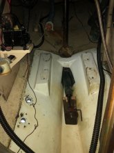
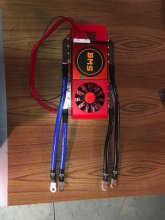
Here is the latest update on my conversion. The motor is installed. I had to extend the stringers and shorten the prop shaft but all of that went well. I changed my plans on 12V power I already had three 12V 79Ah group 24 AGM batteries so I bought a new 12V 79Ah group 24 AGM and wired them in series to give me 48V. The 48V is wired to a switch and then to the 10Kw 48V motor. I then wired the 48V to 12V DC to DC converter directly to the 12V panel. Through the converter the panel is constantly at 13.9V.
The motor and prop are spinning although only for a few seconds at a time since I'm on the hard and no water is in the cutlass bearing. Solar panels are wired in and charging. I'm installing a new 12V electrical panel as well. The old one was working fine but at 41 years old I figured it was time. At this point I'm waiting on the LiFePO4 cells from China, they are not late yet and should be here in the next few weeks. I should have ordered them sooner. Once the cells arrive from China and are balanced and the battery box is built I will install another switch and wire the LiFePO4 battery to the motor. The LiFePO4 battery will only be used for the motor. The AGM battery bank will be primarily used to power the 12V panel but with the flip of a switch it can power the motor in an emergency. With only 79Ah and about 50 of them usable it won't take me to far but again it's for an emergency. The last pic shows the mockup of where the LiFePO4 battery and BMS will be located.


The motor and prop are spinning although only for a few seconds at a time since I'm on the hard and no water is in the cutlass bearing. Solar panels are wired in and charging. I'm installing a new 12V electrical panel as well. The old one was working fine but at 41 years old I figured it was time. At this point I'm waiting on the LiFePO4 cells from China, they are not late yet and should be here in the next few weeks. I should have ordered them sooner. Once the cells arrive from China and are balanced and the battery box is built I will install another switch and wire the LiFePO4 battery to the motor. The LiFePO4 battery will only be used for the motor. The AGM battery bank will be primarily used to power the 12V panel but with the flip of a switch it can power the motor in an emergency. With only 79Ah and about 50 of them usable it won't take me to far but again it's for an emergency. The last pic shows the mockup of where the LiFePO4 battery and BMS will be located.
Similar threads
- Replies
- 3
- Views
- 440
- Replies
- 3
- Views
- 167