danielfp248
Battery researcher
- Joined
- Sep 7, 2020
- Messages
- 429
I agree, Robert does a great job sharing and getting people excited about chemistry. I support his channel and admire his work in this sense.Funny, I’ve had the same feelings. I smile each time he describes the “3 types of people”. clearly, he’s saying that the least trustworthy of the 3 are those involved in battery development - and yet we accept all things on the channel at face value. Reminiscent of the ”frog and the scorpion”.. That being said, I have no particular reason to doubt him.... I think his primary goal (and he‘s quite successful at it) is to inspire others to experiment. To take the published papers and dare to ask “why?”. After all, Flash Graphene synthesis wasn’t optimized on the basis of some quantum revelation. It was a grad student who said something like this... “if we can produce graphene with the power of high intensity lasers, why not try a simple spark discharge?“. Anyone wanting to look at Graphene seriously is in need of a cheap Raman Spectroscope. My old physchem graduate advisor wrote two books on various spectroscopic measurement systems.... he’d be impressed with what you can do with a 3D printer these days!
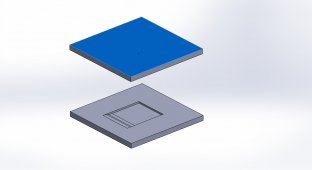
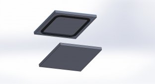
However, his Zn-Br battery designs are just not practical or efficient designs. Those foam batteries have huge energy efficiency losses and the jar designs he shared in his last videos about the topic have abysmal energy efficiencies as well. In both of these designs I would estimate you would get 10-15% energy efficiency out of them, which is not acceptable for a battery application.
Also the Chinese paper that started my journey in Zn-Br batteries is just hype, see this post about my comments on their experimental results https://chemisting.com/2020/09/12/zinc-bromine-batteries-can-they-really-be-that-good/