diy solar

diy solar

MPP-Solar LVX-6048

No, I'm sorry I didn't mean I dont believe you, but I dont believe MPP would make something with that high of idle consumption. Could something be wrong mechanically? You did say it was dropped...
It is possible the L1 and L2 currents have an inductive or capacitive component. In which case the true power loss would be less. I hope this is the case. I'm limited by my available measurement equipment.
 

Attachments

  • IMG_20210521_155308800.jpg
    IMG_20210521_155308800.jpg
    84.3 KB · Views: 18
Well I got a reply and I have to say it was much quicker than I expected.

Hello Andy

The power consumption of the LVX6048 inverter is 140w. How did you measure the 260w? Please provide us with measurements to show this consumption. We think that this value you measured is VA and not Watt.

Thank you.

Best regards,
Andy Y. ¦ Support Team, MPP Solar Inc.
support@mppsolar.com ¦ www.mppsolar.com


Today's readings on L1 and L2 are 0.78 amp and 1.57 amp taken on an Amprobe AMP-25. The volt * amp calculation gives 280 Watts. However that's with a power factor of 1. Applying a power factor of 0.5 gives a value of 140 Watts. That may or may not be the correct power factor. I have
sent this information back to MPP for clarification.
AxH, thanks for the update. I'm looking forward to clarification as well. For those casual readers a power factor of 1 is were the current sin wave and voltage wave are in phase and represents a resistive load. A leading current with phase angle of 90 degrees to voltage would be a capacitive load. A 90 degree lagging current an inductive load. These leading or lagging currents are reactive loads. Thinking on the fly here, Let's assume the utility at 240 Vac rms with neutral connection. Inside the inverter is a 120 Ohm resistors from L1 to N and another from N to L2. The real L1 current would be 120V/120 Ohms or 1 Amp rms. Same for L2 current. Now if we added a capacitor in parallel will one resistor and the reactance of the cap at 60hz were 120 Ohms leading (current 90 deg) an additional 1Amp rms of capacitive current is in parallel with the 1 Amp resistive current. I think we get a current vector product of 1.41 Amps with leading 45 degree angle. A clamp on current meter would respond to the max B field of the wire it is measuring, or 1.41A. The extra energy stored in the cap during charging is later returned back to the grid when the L1 voltage is falling so the inverter does not actually consume this power.

In the case of an H bridge FET chopper connecting a capacitor bank to a grid you would think it could maintain an effective resistive load to the utility both when it consumes or sources power to the grid. It would be nice to check the waveform characteristics including power factor under light and heavily loads as well as light and heavy grid tie function. Radiated emissions is another.

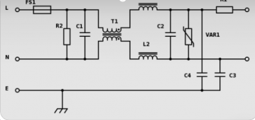
Continuing, I guess it's possible the utility input filter is the source of the reactive component. These are usually a parallel cap, common mode inductor and another parallel cap. They are sized for filtering at the max current rating. At idle currents they could pose a strong reactive current relative to the idle input current of a few amps. I think this explanation fits our observations.
Cheers.
Typical input filter.
 

Attachments

  • Screenshot_20210617-213234~2.png
    Screenshot_20210617-213234~2.png
    44.2 KB · Views: 11
Hello Andy

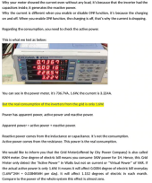
When inverter's under bypass mode, the inverter has input capacitors which will store energy there, but NO REAL WORK HAS BEEN DONE. That's why when you use a simple volt meter like the one shown in the picture, the value you get is actually VA, not WATT. Utility company charges users based on REAL WORK which is WATT. In the laboratory, we use a very sophisticated equipment that test both VA and WATT at the same time. Simple meters like the ones you have cannot do that. anyway I send you an attachment you can take a look it explains the same issue to another customer who had the same question (on a different inverter). There's no problem with the inverter so please don't worry about this. ALL OUR INVERTERS UNDER BYPASS MODE, INCLUDING MANY OTHER INVERTERS ON THE MARKET, ARE THE SAME WAY.

1624016718698.png

I hope it helps you.

Thank you.

Best regards,
Andy Y. ¦ Support Team, MPP Solar Inc.
support@mppsolar.com ¦ www.mppsolar.com
 
Hello Andy

When inverter's under bypass mode, the inverter has input capacitors which will store energy there, but NO REAL WORK HAS BEEN DONE. That's why when you use a simple volt meter like the one shown in the picture, the value you get is actually VA, not WATT. Utility company charges users based on REAL WORK which is WATT. In the laboratory, we use a very sophisticated equipment that test both VA and WATT at the same time. Simple meters like the ones you have cannot do that. anyway I send you an attachment you can take a look it explains the same issue to another customer who had the same question (on a different inverter). There's no problem with the inverter so please don't worry about this. ALL OUR INVERTERS UNDER BYPASS MODE, INCLUDING MANY OTHER INVERTERS ON THE MARKET, ARE THE SAME WAY.

View attachment 53278

I hope it helps you.

Thank you.

Best regards,
Andy Y. ¦ Support Team, MPP Solar Inc.
support@mppsolar.com ¦ www.mppsolar.com
Txh, Thanks for sharing. This is encouraging news from MPP. It would be nice to know real power draw for LVX6048 in standby mode.
 
Bad news. When I hooked it up everything was going great until I put a load on it. There is an intermittent ticking and my magnetic/low watt fans were acting weird, it wan’t until it got dark I realized what was going on. Needless to say something is amiss with the unit, it must have happened when it got dropped.

It really sucks because the charge controller was working well into the early evening, whereas the Renogy unit shut down pretty early.

Videos attached.


I’m having the same problem with a ceiling fan too. It only does it if the inverter is on battery or PV, if is on bypass the fan works just fine.

Anyone else is having the same problem???
 
Is the fan the only load? If so, try adding a resistive load just in case the fan is not allowing it to exit low power mode...
 
Is the fan the only load? If so, try adding a resistive load just in case the fan is not allowing it to exit low power mode...
Negative, the LVX 6048 is providing power to the house main power panel, however the fan is the only appliance in the circuit after the light interruptor.
 
How are people mounting these? The holes are much closer together than 16" (stud spacing). Is there a bracket that works?
 
Also is inputting 120V fine for the AC input? The manual actually only specifies 120V input but there's two hot inputs so I'm not sure if that's a manual error.
 
It's the split phase dual input for North America... The two hot inputs provide 240v. Are you in US/Canada?
 
It's the split phase dual input for North America... The two hot inputs provide 240v. Are you in US/Canada?
I see. It's specifying the voltage for each hot input. Is only using 1 hot input fine if grid power will only be used for charging the battery in standby mode?
 
The brochure says "AC Input Voltage 110 VAC (P-N) / 220 VAC (P-P)" so looks like you can power it with 1 Neutral and 1 Hot 110v (or 115 or 120). There's nothing to say the inverter won't charge the battery from 110v AC input in standby. The manual diagram indicates it will.
 
Last edited:
I have one of these inverters and will hopefully have it up in the next month, I'll try and figure out if they do have high idle watt usage.

Could one simply not see how much it drains a battery overnight (one that is stable) with no loads hooked up? This would give a good rough idea, right?
 
I have one of these inverters and will hopefully have it up in the next month, I'll try and figure out if they do have high idle watt usage.

Could one simply not see how much it drains a battery overnight (one that is stable) with no loads hooked up? This would give a good rough idea, right?
info from MPP. The no load power consumption is in between 25- 40 watt.
but I find this page easier to find the specs https://voltronicpower.com/en-US/Product/Detail/InfiniSolar-VII-6KW-(Split-Phase)
 
According to Ian at Watts247 this is normal for this inverter.

During sunlight hours not a problem, I can power from the panels.
Overnight its going to suck more power from the (expensive) grid than I was expecting.

Hopefully what I save during the day will offset what it uses during the night.
Have to buy some batteries I guess.
Considerably more than my LV6548's.
 
Back
Top