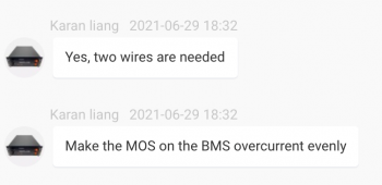
Is there a protocol for the Deye available?The BMS could choose the protocols above through software(with admin account).
You are using an out of date browser. It may not display this or other websites correctly.
You should upgrade or use an alternative browser.
You should upgrade or use an alternative browser.
Seplos CAN BUS RS485 48v 200A 8S-16S BMS
- Thread starter Firechief
- Start date
shavermcspud
Solar Enthusiast
- Joined
- Mar 12, 2020
- Messages
- 575
Thought id chime in here, I purchased the Seplos 16s BMS 100amp foor $125 after seeing a nice guy called Tony on here saying his worked great with the same inverter I have, it arrived yesterday, thought this would be the missing link between my current CAN compatible ME3000 storage inverter and my Lifepo4 pack. Since install Ive had all manner of issues with mine, potentially a faulty unit but support are next to useless.
Although it communicates fine with my inverter now on Canbus as a pylontech pack it will not discharge the pack for me, it will charge up fine as it did this morning via PV but anytime its requested to discharge the BMS goes in to shutdown with random errors such as output short circuit, cell 1 & 2 empty errors despite them being at 3.45v, manual is the normal badly translated English, software is ok but again littered with errors and words that don't mean what the Chinese think they do with absolutely no manual for the software to explain what the functions actually do or what theyre supposed to mean. On the fence with this one at the moment.
Although it communicates fine with my inverter now on Canbus as a pylontech pack it will not discharge the pack for me, it will charge up fine as it did this morning via PV but anytime its requested to discharge the BMS goes in to shutdown with random errors such as output short circuit, cell 1 & 2 empty errors despite them being at 3.45v, manual is the normal badly translated English, software is ok but again littered with errors and words that don't mean what the Chinese think they do with absolutely no manual for the software to explain what the functions actually do or what theyre supposed to mean. On the fence with this one at the moment.
houseofancients
Solar Wizard
can you order them a piece now, or still moq of 5 ?Just pulled the trigger on a Seplos 200A BMS. Has anybody found a good enclosure that is at least dust proof?
shavermcspud
Solar Enthusiast
- Joined
- Mar 12, 2020
- Messages
- 575
You can order single unitscan you order them a piece now, or still moq of 5 ?
houseofancients
Solar Wizard
please let us know how it rins once you have it installedYou can order single units
shavermcspud
Solar Enthusiast
- Joined
- Mar 12, 2020
- Messages
- 575
I have installed it and it doesn't work.please let us know how it rins once you have it installed
Support are insisting its my inverter that's at fault despite it working absolutely fine with my old BMS and existing batteries.
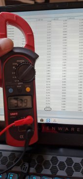
Under standby with no draw the BMS shows all the cells at the correct voltage, as soon as any discharge is applied cell 1 reads 0.210v on the BMS and cell 2 reads 0.00v, I have sent them this picture of my volt meter reading at the same time, my DVM shows the correct cell voltage but the BMS seems to think its 0.210v

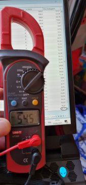
The other issue is the whole pack voltage, again under NO load the BMS shows 54.5v and under load is shows10.3v total pack voltage but my DVM reads 54.5 still at the same time.

Clearly a fault with the BMS but they wont aknowledge it at the moment.
houseofancients
Solar Wizard
just because you have a faulty one, doesnt mean they dont work at all.I have installed it and it doesn't work.
Support are insisting its my inverter that's at fault despite it working absolutely fine with my old BMS and existing batteries.
Under standby with no draw the BMS shows all the cells at the correct voltage, as soon as any discharge is applied cell 1 reads 0.210v on the BMS and cell 2 reads 0.00v, I have sent them this picture of my volt meter reading at the same time, my DVM shows the correct cell voltage but the BMS seems to think its 0.210v
View attachment 53804
The other issue is the whole pack voltage, again under NO load the BMS shows 54.5v and under load is shows10.3v total pack voltage but my DVM reads 54.5 still at the same time.
View attachment 53805
Clearly a fault with the BMS but they wont aknowledge it at the moment.
i do hope however you get the issue worked out.
maybe a silly question, but are you sure you have hooked up all balance leads according to spec, and set the dip switches correct ?
also, chances are, the person you're talking to doesnt speak english very well, and stuff gets lost in translation
shavermcspud
Solar Enthusiast
- Joined
- Mar 12, 2020
- Messages
- 575
I appreciate that, I didn't state that they don't work at all, just mine, others have had success with theirs. I'm making a point that a relative newcomer to market has quite bad customer service.just because you have a faulty one, doesnt mean they dont work at all.
i do hope however you get the issue worked out.
maybe a silly question, but are you sure you have hooked up all balance leads according to spec, and set the dip switches correct ?
also, chances are, the person you're talking to doesnt speak english very well, and stuff gets lost in translation
If you read my above post again properly, you will see, the cell voltages all show correctly when in charge mode or standby mode so yes balance leads are all wired correctly, This isn't my first battery build, again dip switches yes for single pack, but irrelevant for the topic we are discussing.
I have just confimred its not the inverter by borrowing a 2.4kw pylontech stack which worked straight away.
weirded
New Member
- Joined
- May 8, 2021
- Messages
- 145
Was able to order a single one (“sample”) no problem.can you order them a piece now, or still moq of 5 ?
weirded
New Member
- Joined
- May 8, 2021
- Messages
- 145
On a related note - anybody found a good enclosure for this BMS? My install is going into a garage, so I don't just want an exposed circuit board hanging around. My tentative plan was to find a plastic box in roughly the right size on Amazon and drill/cut holes for the various ports (RS485, CAN, etc), as well as the display.
Any tips/pointers would be appreciated.
Any tips/pointers would be appreciated.
shavermcspud
Solar Enthusiast
- Joined
- Mar 12, 2020
- Messages
- 575
I'm working on a 3D printed enclosure for it as we speak, as soon as my replacement arrives this Wednesday (and hopefully works) I will let you know how it fits.On a related note - anybody found a good enclosure for this BMS? My install is going into a garage, so I don't just want an exposed circuit board hanging around. My tentative plan was to find a plastic box in roughly the right size on Amazon and drill/cut holes for the various ports (RS485, CAN, etc), as well as the display.
Any tips/pointers would be appreciated.
weirded
New Member
- Joined
- May 8, 2021
- Messages
- 145
shavermcspud
Solar Enthusiast
- Joined
- Mar 12, 2020
- Messages
- 575
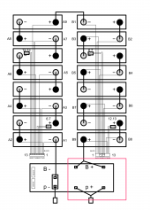
I had the same issue, I didn't seem to make any difference using one or both on a Y harnessJust noticed this oddity on their wiring diagram. Anybody know what to make of this? Do they want me to connect the positive to more than one of the terminals for some reason?
View attachment 54510
Physically, the board looks like this:
View attachment 54511
Are they worried that one of the lugs can't carry enough current through the board?
houseofancients
Solar Wizard
probably just making very sure the cable and lugs will not be a resistance pointJust noticed this oddity on their wiring diagram. Anybody know what to make of this? Do they want me to connect the positive to more than one of the terminals for some reason?
View attachment 54510
Physically, the board looks like this:
View attachment 54511
Are they worried that one of the lugs can't carry enough current through the board?
weirded
New Member
- Joined
- May 8, 2021
- Messages
- 145
I may just get a copper bar and put it across all three points to be sure. This is going to be used for a pretty beefy battery pack (16s 400Ah) so may as well minimize heat and resistance...probably just making very sure the cable and lugs will not be a resistance point
houseofancients
Solar Wizard
yeah, i truely like this bms, and have yet to hear back from tye sample request i did with seplos.
so we'll see.
will be following this threat with much interest
so we'll see.
will be following this threat with much interest
shavermcspud
Solar Enthusiast
- Joined
- Mar 12, 2020
- Messages
- 575
Just thought I would update everyone, after lots of back and forth and finally getting through to a very helpful support guy at Seplos we run tthough all the tests he asked, he confirmed it was faulty and passed the email chain back to Adam in sales who straight away sent me a new one, they sent it priority air mail and arrived in the UK in three days flat. I have just installed it and its working exactly as described
weirded
New Member
- Joined
- May 8, 2021
- Messages
- 145
Just thought I would update everyone, after lots of back and forth and finally getting through to a very helpful support guy at Seplos we run tthough all the tests he asked, he confirmed it was faulty and passed the email chain back to Adam in sales who straight away sent me a new one, they sent it priority air mail and arrived in the UK in three days flat. I have just installed it and its working exactly as described
Couldn't agree more, I've been speaking with Seplos via the Alibaba chat function and they have been very helpful answering lots of detailed questions like "What type of connector is used to the balance cables".
Similar threads
- Replies
- 6
- Views
- 1K
- Replies
- 2
- Views
- 268
- Replies
- 1
- Views
- 105
- Replies
- 9
- Views
- 870
- Replies
- 6
- Views
- 883


