diy solar

diy solar

EVE-280 cells should these be clamped tight or spaced for expansion?

Hello guys.

I was in the same situation a month ago, and after my first top balance discovered that the cells can swell up a lot, for example, this cells use to sit perfectly flat, and this happened after a low C rate charge, a couple of mm of separation:

View attachment 15534

Its not that bad and its between spec, but aside from the recommendation from EVE of adding pressure, the nordkyn desing web also recommends a fixture to prevent "delamination" from the expansion / contraption cycles.

Cells are probably going to be OK with, or without it..., but i invested a lot of $$ on my system and want to make it last as long as possible. So if i can spend a couple of days and some dollars to make a fixture and just maybe get 500 - 1000 more cycles, ill do it.

This is some solutions from marinehowto and nordkyn desing:

View attachment 15535View attachment 15536


Very easy to make, only problem would be the heat disipation that migh drecrease the lifespan a little bit (Probably neglilible with our lower C rates)

I decided to make a full enclosure:

View attachment 15537
View attachment 15538
View attachment 15539

  • Have aluminum flatbars and "T" extrusions to allow some airflow betwen cells, so heat wont be much of a problem.
  • Can mount both horizontallly and vertically, also could fix to the wall.
  • Can "easily" transport the full pack to connect between systems. (Probably not needed for a lot of people, but usefull for me).
  • Can easily change the BMS, as the leads are connected to a connection bar.
  • Looks better!
And as you can see, i have 4 x threaded rods in the design, so i can put the 300KGF if i want, in practice i just compress them a bit as i dont know how to calculate or measure that... i guess you can calculate that with a torquimeter or just measure with a pressure plate.

The cell walls stay completely flat with the middle flatbars and resistant aluminum structure in both sides.

So far im happy with the build!
Most impressive build I've seen yet, very polished high quality over all the plywood bird houses I've seen.
I really like the middle flat bars to allow air flow. What are the dimensions of the complete box?
I'd buy it ready to go out with your design. my batteries are on order. what's the thickness of your aluminum spacers, I'm wanting exactly this setup!
 
You are making me blush!.. thanks ;)

So far the setup has been working perfectly.... if you have the time its a good option but involves a couple of days of work. Ive seen some easier to make setups in this forum, and some guy was even talking about selling them.. Maybe someone else can link it, i remember it was a metallic end platter where you can put your threaded rods.

Anyways, about your questions, the total size its 69 x 22 x 28cm (LxWxH)... and the aluminum spacers are 1/16 (Around 1.5mm).

You can find attached the Blender file, my plan was to improve the setup a little bit (Making it easier to build) and upload this to the forum with nicer diagrams / plans, but i haven't had the time.

The .blend has all the dimensions, if you havent used blender before you can learn the basics in 30m if the model its helfpull.

Greetings!
 

Attachments

  • Battery Pack.blend1.zip
    234.8 KB · Views: 98
You are making me blush!.. thanks ;)

So far the setup has been working perfectly.... if you have the time its a good option but involves a couple of days of work. Ive seen some easier to make setups in this forum, and some guy was even talking about selling them.. Maybe someone else can link it, i remember it was a metallic end platter where you can put your threaded rods.

Anyways, about your questions, the total size its 69 x 22 x 28cm (LxWxH)... and the aluminum spacers are 1/16 (Around 1.5mm).

You can find attached the Blender file, my plan was to improve the setup a little bit (Making it easier to build) and upload this to the forum with nicer diagrams / plans, but i haven't had the time.

The .blend has all the dimensions, if you havent used blender before you can learn the basics in 30m if the model its helfpull.

Greetings!
wow. ... that zip file (attachment) was a waste of my time (for me) .... maybe a *.jpg version might be better next time.
 
Strange; opened fine, no special software, standard Win10 install on this machine.
 
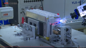
The following video shows how EVE compresses 10 cells using a spindle. Next, they laser weld the case while under pressure. Random note: see those rulers mounted on the table. Also note that no electrical insulators *seem* to be added between the cells, apart from of the blue (or yellow?) foil.

(below is a still from the same video)

EVE battery case welding.PNG
 
Blue and yellow.
Blue on the cells, yellow at the sheets that are pressed against the blue wrapped cells.

I need to get one of those laser welders!!
They are awesome!! :)
 
The following video shows how EVE compresses 10 cells using a spindle. Next, they laser weld the case while under pressure. Random note: see those rulers mounted on the table. Also note that no electrical insulators *seem* to be added between the cells, apart from of the blue (or yellow?) foil.

(below is a still from the same video)

View attachment 39899
I bet those battery packs are noticably more expensive than the ones we are buying, plus for electric vehicles. The biggest issue I have with this compression idea is having solid bus bars that get clamped in place on the 280Ah cells I have that have slightly wavy or slightly puffed out sides (not perfectly flat planes that were that way I received them); ... that may or might not change when running larger amps in and out of em (mine might only up to 0.5C). What kind of stress might that put on battery terminals? or what what might be easy flex bus bar option? ... I will figure out what I am doing w this compression idea when I build my stack battery rack and integrate 2nd 24v x 280Ah set for 560Ah for a sitting very still solar application.
 
Last edited:
Terminal stress seems to be a common concern.
Rather than busbars, several members are using braided copper.
Flexible welding cable with crimped tinned lugs seems like the simplest solution.
Make them longer than needed to allow for movement.
 
The following video shows how EVE compresses 10 cells using a spindle. Next, they laser weld the case while under pressure. Random note: see those rulers mounted on the table. Also note that no electrical insulators *seem* to be added between the cells, apart from of the blue (or yellow?) foil.

(below is a still from the same video)

View attachment 39899
Good find. I'd like a closer look at one of those packs, I'm assuming the yellow stuff is some kind of foam as mentioned in this thread:

In relation to eve lf280:

The pressure on the terminals was the first thing I noticed when I test setup my pack, and heard movement when I removed the busbars from a fully charged pack.

I also noticed that a fully charged pack that i'd tightly clamped with 10mm Alu plates and m6 rod, was loose on discharge. Must clamp at the sweet spot of charge/expansion.

As far as the terminals go, from a dismantling video of a 100ah cell I saw, it looks like the connection from terminal to cells is flexible, but I still would be concerned about work hardening and possibly fracture and leaking of the case after multiple cycles.

So all of this brings me to the conclusion that I will be installing 3mm foam between all cells, the Saint Gobain Norseal looks hard to find and expensive, so will be using Zotefoam. I will use springs to get the right clamping force, then remove them one by one.

Also will probably ditch busbars for tube lugs and braided cable. When I assembled my first pack, I noticed the planes of each terminal were not parallel, with only low torque forces on the terminals allowed, there is no way a bus bar would bend to the terminal face, or pull the terminal to the busbar.(I'd love to find out that the terminals are designed to accommodate movement) My observations from trying to hone terminal pairs parallel showed me that without this modification, busbars are only likely to get about 30 to 40% contact area to terminal face, depending on deviations of the terminal plane. But in my case it was pretty consistent.

So, there's my tuppence worth. ?
yes, the stress on the small 6mm studs is a major concern - I agree. I also was looking at the idea of more flexible cell interconnects. the breaded ones seem to be a possibility. I also was looking at trying to crimp cables and lugs for interconnects between the cells. the compression jig is still a good idea with some sort of slick insulating dividers.
the electrical engineer was also noting that braided or flexible interconnection should be used between cells.
each to their own - more than one way to solve or improve upon the design of the aluminum prismatic cell to battery build issues by the DIY community brainstorming together.
glad you brought this topic up as it really has not been properly addressed in the forum articles that I have read.
I learn new things every day.
studying up on engineering and physics lately in my relaxing time.
keep up the good work!?
I do note that there is less swelling if you do not change the cells too fast (too high of a C rate). the sbms0 don't allow mine to charge above 3.55 volts as the LiFePO4 prefer to be around 3.4 volts per cell for a longer life-span and not at the maximum 3.65 Volt often quoted.
the 3.65volt should only be charged at the initial top balancing in an attempt to keep the cells closer together, but there will always be a cell or 2 that seems to race to the upper limits 1st. that is why one needs the BMS to monitor and balance the cells a bit.
thanks for your tuppence! glad to see it!?
 
Just an aside.
I was looking through this thread but did not read every post.
This may have already come up.
A Kgf is 1 kg (mass) times 9.8 m/s^2 (acceleration) which gives a force of 9.8 newtons. which is 2.2 lbf
So 300kgf is 661 lbf, divided between four bolts/ rods. So that gives a total of 165 lbs tension per rod (1/2 inch) which requires about 10-inch pounds of torque. So don't over tighten ;-)
 
Hello Andy

What formula are you using for tension -> torque?, want to check my 3/8 rods, maybe i over thighten ;)
 
If you are going to do fixed compression without using springs .... the the pressure should be applied with the pack fully charged. This will prevent the compression from being too high at higher states of charge.

While 12 PSI is the ideal ... anything over 17 PSI will cause increased pack degradation instead of extending cycle life.
 
The fixture used by the mfr has compression on the short sides as well. Most of the fixtures I've seen on the forum only clamp the longer faces. Any concern there? I'm charging mine up for the first time. Just using thick plywood faces and clamps for the top balancing, 4 cells at a time.

Also, I see a lot of discussion of foam dividers and aluminum strips and T-extrusion for the corners. Any thoughts on using aluminum plates with extensions for heat removal from the interior. I guess the thing I would be most concerned about is anything getting in between and shorting the cell bodies together via the aluminum. Seems unlikely if you're careful about assembly though.
 
Unless the C rate is high, end compression of cells shouldn't be an issue. The aluminum case in which it is packaged won't flex much on the short end.

Also, interior heat shouldn't be a problem at low C rates. As long as the pack is under 30°C the cells will sustain low degradation. A BMS with a temperature probe will protect the pack.

A dielectric separation is favored over metal. PCM foam is used by some in the vehicle industry, where the C rates are higher. You may find useful this link on thermal behavior.
 
High C-rate is mostly creating larger heat then slow charge.

For compression, the thin aluminium walls casing (not CalB) is NOT intended for home use.

It is intended to have structural strength improvement form manufacturers

That's us now... Manufacturer.
Adding a di-electric sheet is always smart. Anti-static plastic would work great.

Casing won't make a short it's negative, if conductive at all.
Even then..
It won't hurt. The thin blue plastic is not really high capacity protection.
(280Ah is in my book high capacity)

Side compression..
Not so important.

The compression is there to prevent delamination.
Delamination does 2 things:
- reduce battery capacity
- increase risk of instant selfdischarge: all contained current converted to heat.

Once bloated....
It's not as safe as it was before bloating.
Slightly bloat, like about one mm., Not a problem.
Large bloat like over 3mm....
Challenges!

Best is to mimic the factory original construction with the materials at hand.

Instant selfdischarge will reach temperatures way over 500c, (but under 660C) infection the neighbor cells, and perhaps enough heat to self combust the plywood.
Or (di-electric) grease, what usually starts to ignite at 350-450C
 
Back
Top