diy solar

diy solar

Dump all excess PV to air heater?

Much more on this topic can be found on forum.midnite.com and on solar-electric forum
Thanks @Tecnodave, this seems to be the most helpful link relating to that: http://midniteftp.com/forum/index.php?topic=3881.msg46634#msg46634
As well as what is linked from that message a large amount of references listed here: http://midniteftp.com/forum/index.php?topic=3881.msg37894#msg37894

There still seems to be concern about batteries not being properly charged when using diversion load based on battery voltage. Maybe this isn't as much concern with LiFePO4's? But it does seem like the ideal situation is if the batteries weren't involved at all which @efficientPV and I think @FilterGuy as well. Your setup is all custom made though, right @efficientPV?

Having diversion from battery though appears it would have some advantages for systems that have multiple charge controllers and you would better know the voltage range the diversion load would have to deal with.
 
You could sense PV voltage. When it is above Vmp, less than 100% is being harvested.

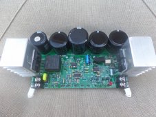
I do it. Sense the PV voltage and when it goes above power point it proportionately diverts power to a heating element enough to bring the voltage to juat above the power point voltage of the panels. No charge controller of batteries are involved, just direct power from the panels to the heater. You always have full battery and not unnecessarily heating up CC. DIVERSION FROM BATTERIES IS NUTS. I can divert as little as 5W. The ACTii AC7391 can do it in fixed mode but it is limited to about 8A. I use my own design for 12A diversion up to 200V (120V array). Two wires in, two wires out and set the voltage.
View attachment 58606
Can you share the design?
 
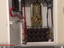
There are designs out there if anyone bothers to look. Only a hand full have been interested. below is a couple of pictures that have been sent to me of their builds. This board is a particular good design with the bells and whistles. It will go into production some day when I find someone to take it over. I bought parts to build over 100 of them and have to recover that cost. A few evaluation are available at lower cost to those who will do a video or write up. Most heat water with them. One person does floor heating and another heats water, but it switches over when he turns on his electric clothes dryer.
FLRICH_1s.jpgLITH_1000.PNG
 
Apples and Oranges.....

Doing load diversion as a stand alone is way different than loading down the panels so that the Maximum Power Point Controller cannot find the MPP due to the loading on the panels by some secondary controller.

I have discussed this scheme with lead designers of the MidNite SCC and every engineer agrees that putting a controller between the SCC and the batteries will result in the SCC will not be able to correctly find the Maximum Power Point.

There is nothing that you can put between the panels and the MPPT controller that will increase the output of that MPPT SCC. It will decrease the efficiency.

This comes from two of the best minds in Solar Charge Controllers........The Gudgels.........Trace....Outback....MidNite
The most innovative folks in the solar business.....

My needs are electricity , not diversion, but i have both.
Disclaimer......I AM BIASED.....I have worked on MidNite pre production prototypes, I helped with the Kid program and am still awaiting my Rosie the Inverter....I have seen the good, bad, and ugly
 
Last edited:
Sounds like Indiana Jones.... "We got top top people working on it. What toy say is true if you have two mMPPT controllers. Once you go a little above MPP voltage, MPPT is no longer working. CC is just drawing what it needs and the panels float to whatever. You don't get everything extra, just most of it. You are just not understanding the principals. I have three of these diverters on the same array as the charge controllers and everyone is happy. You just never asked the right question to them.
 
Thank you just the same, I choose to beleive the engineers at MidNite who say in unison not to put anything brtween a MPPT controller and the array that it is controlling..., not panel optimizers, not anything......but then i do not have any price point equiptment, Its all the best of the best...MidNite,Outback,Trace,Magnum Energy, Morningstar, Exeltech, Dynamote Brutus.......the very first high/low frequency inverter.

Read the wiki at wikipedia: maximum power point controllers.....
 
Personally I plan on experimenting with Peltier Heat Pump for divert load to simultaneously heat and cool water in separated insulated containers. Should work the same with whatever load be it a heater or whatnot.

I intend on using battery pack voltage sense to determine when the arduino will turn the load on or off.

Given knowledge of the LFP charge curve, simply divert load when pack exceeds 3.375 volts per cell. Adjust that threshold to optimize.

I’m too chicken to muck with the higher voltage PV side so I’m sticking to battery diversion due to lower and more consistent voltage.
 
Peltier heat pumps are horribly inefficient, modern dc permanent magnet refrigeration is far, far, far more efficient than Peltier heat pumps
 
Peltier heat pumps are horribly inefficient, modern dc permanent magnet refrigeration is far, far, far more efficient than Peltier heat pumps
Peltier run at *high voltage* is horribly inefficient.

Peltier run at 1-2V per 127 junction module is efficient comparably so to refrigerant based compressor units. CoP of 2-4 can be achieved which is comparable with compressor.

Edit: trying to provide actionable info..

Peltier are sold in grades based on their resistance. The rating is for how many amperes a single module can handle. For the 40x40mm modules the lowest efficiency rating is 3 ampere and the highest efficiency is 15 ampere.

15 ampere modules have ~1 ohm ac resistance
6 ampere modules have ~2 ohm
it just gets worse the lower ampere rating you go.

this means twice as much Joule heating if one sources TEC1-12706 instead of TEC1-12715 modules. Joule heating is inefficient compared to pumping heat.

not all peltier are the same. they can operate efficiently. happy to give more advice.

peltier element have a Max Voltage rating. Often 15.4V. do not run the module at this voltage! run at 10-20% of Vmax. this is how to access Efficient Peltier Life. ✌️

The trick is that the modules can be stacked to sum the pumped heat. When run at 10-20% of Vmax the temperature difference across a single element is too low alone.

With ambient air 25C I’ve cooled water down to 7C and heated up to 70C using a stack of 20 units of TEC1-12715 modules arranged five side by side and four layer between two aluminum water blocks. It uses 80-100 W and it drives the peltier direct from the LFP battery. solid state heat pump

3S LFP battery. 9-11V. Using an H-bridge to drive all twenty peltier modules as one string. Electrically like a solar string it’s 5S4P wiring.

9/5 = 1.9 V per peltier module
11/5 = 2.2 V per peltier module.
1628037910720.jpeg

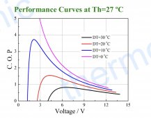
This is a coefficient of performance vs voltage graph for a TEC1-12715. Check the blue curve. It represents 10C delta temperature which is good for four layers. 4 layer x 10C = 40C max delta. Can get down to freezing if it’s ~30C ambient..

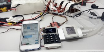
Anyways.. here’s a pic of the test setup:
1628038622334.jpeg
the center display shows hot vs cold (primary vs secondary) side temp. 34C hot side 10C on cold side with 78W usage.

I was able to get that same side from as low as 7C all the way up to 70C. All while using <100W I think it’s fairly efficient. Haven’t evaluated CoP quantitatively yet. I expect CoP 1.5-3 depending on specific operating temperature.
 
Last edited:
What kind of compressor....? Not a Danfoss permanent magnet motor, My Grape Solar 5 cu.ft. danfoss powered referigerator uses 42 watts with a 15-20% duty cycle, my coleman cooler uses 48 watts non stop 4.0 amps at 12 volts (it does not have a thermostat).....and it will not freeze using 5 times the power of the Danfoss compressor.

I have never seen a Peltier cooler that is as efficient as a Grape Solar or Sun Danzer, can you name a product that uses Peltier technology that uses less power than a SunDanzer..........commercial product with a listing available today.....I would like to see that published information
 
I can’t name a product; all the commercial peltier fridges I’ve seen are total crap and not worth anyone’s time. they all appear to use a single layer, a hopeless endeavor. thin insulation. futile.

that’s why I’m building it myself ?

i’m building a fridge using 2” of vacuum insulated panels on all sides.. ~R40.

this same TECnology will work perfectly for my hot water needs if scaled up.

another issue with commercial peltier fridges that make them silly is that the peltier directly interfaces with the inside volume!! heat flows rapidly back into the box!! futile.

i plan on using two water circulation loops. the inside cold area will be cooled by pumping cold water through silicone tubes and into an aluminum water block and maybe copper heat spreader..

by modulating the pump you can modulate the insulation. this is fundamentally superior principle of operation compared to direct conduction peltier fridge as you will find in the “travel coolers” aka battery killing food spoilers
 
Last edited:
I can’t name a product; all the commercial peltier fridges I’ve seen are total crap and not worth anyone’s time. they all appear to use a single layer, a hopeless endeavor. thin insulation. futile.

that’s why I’m building it myself ?

i’m building a fridge using 2” of vacuum insulated panels on all sides.. ~R40.

this same TECnology will work perfectly for my hot water needs if scaled up.

another issue with commercial peltier fridges that make them silly is that the peltier directly interfaces with the inside volume!! heat flows rapidly back into the box!! futile.

i plan on using two water circulation loops. the inside cold area will be cooled by pumping cold water through silicone tubes and into an aluminum water block and maybe copper heat spreader..

by modulating the pump you can modulate the insulation. this is fundamentally superior principle of operation compared to direct conduction peltier fridge as you will find in the “travel coolers” aka battery killing food spoilers
Yep, you said it....all the commercial peltier coolers are krap...........I do not need to waste my time with that, I have been using Danfoss powered referigerator for 12 years now.......
 
not all peltier are the same. they can operate efficiently. happy to give more advice.
If I order from my favorite Chinese store-

10pcs/lot TEC1 12715​

and my voltage range is 12.6-14.8v or 0-21v how would you arrange these?
Application- decide during transit time.
 
If I order from my favorite Chinese store-

10pcs/lot TEC1 12715​

and my voltage range is 12.6-14.8v or 0-21v how would you arrange these?
Application- decide during transit time.
please help me understand these two voltage ranges.

based on bench power supply experimenting i decided 1.9 volt to 2.2 volt per TEC1-12715 in series is the band i would focus on for maximum efficiency without having to stack too many layers. even 1.4 volt applied resulted in a noticeable amount of heat being pumped.

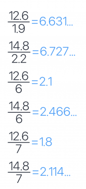
napkin math for 12.6 volt to 14.8 volt:

1628049382236.png
thus, i suggest you evaluate 7x TEC1-12715 in series for this voltage range. that will result in 1.8-2.1 volt per TEC1-12715 and thus highest efficiency.

0 volt to 21 volt:

0 volts would result in no heat being pumped, so i would avoid that and focus on the 21 high end.

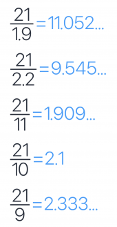
napkin math:
1628049803838.png
thus i would suggest you evaluate 9x TEC1-12715 for this voltage range. that will give you strong yet efficient heat pumping at 21 volt input to 9 series peltier, at 2.33 volt per TEC1-12715. Performance will go down as the voltage goes down.

hope this helps, good luck with any experiments you do.

https://diysolarforum.com/threads/solving-the-climate-control-crises.23322/post-291839

https://diysolarforum.com/threads/i...on-setup-using-solar-energy.22301/post-263312

two other posts with additional info.

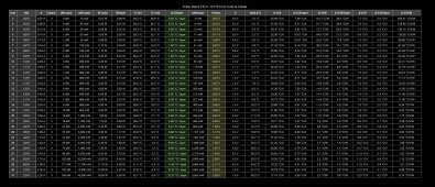
here’s my experimental data spreadsheet from testing 3x TEC1-12715 in series stacked on each other with thermal pad between each. used a cpu cooler with heat pipes.
https://diysolarforum.com/threads/will-im-sorry-but.525/post-288747

1628050830735.jpeg
 
Last edited:
curious carbon,

I did hong haul sailing for a while, that is where i saw the best of the peltier coolers, installed through hull, if you do develop this to a commercial product there is a ready market. After 15-20 days you would do anything for some fresh food......
 
installed through hull
wow cool!!! dissipating heat directly through the hull sounds so cool! either through the hull or by drawing in sea water through a heat exchanger. i would worry about biology clogging a pumped heat exchanger. thank you for mentioning this interesting application!
 
and it worked very well, though it was expensive, too long to remember a number but at 20 days we had fresh food, cooler built into yacht with maybe 5-6 inches insulation, thru hull radiator , the yacht had a small wind generator for power, i just was along as crew, not my boat, i suffered with a ice chest on my small sailboat. ....ugh.
 
and it worked very well, though it was expensive, too long to remember a number but at 20 days we had fresh food, cooler built into yacht with maybe 5-6 inches insulation, thru hull radiator , the yacht had a small wind generator for power, i just was along as crew, not my boat, i suffered with a ice chest on my small sailboat. ....ugh.
thank you for sharing your experience, very interesting to learn about challenges encountered during extended sailing. shame they didn’t have you set up with one too. sounds like they at least shared a bit ?
 
I have a Victron system and was wondering if there is any example of how I can make sure the solar charge controllers are always running at 100% and any excess the battery does not need gets diverted to some sort of electric heater to heat air. I used to have a system that used relay when the batteries were full but that would cause some power to be pulled from the batteries and it was always either fully on or off. If I have a 2kW heater for example, it would turn the full 2kW heater, wait for the voltage to drop on battery, then turn off when the battery voltage was below a setpoint. so you'd get wild fluctuations... I want the battery to stay 100% full and dump in this case everything else to the heater. Does someone know how you'd set up such a system?
I am planning on using peltier to simultaneously heat and cool separate loops of water efficiently.

Peltier are actually strictly more efficient than resistive heaters. Fun fact!

This is because they act as both a typical resistor that does 100% efficient Joule Heating but also Joule Pumping!

All this assumes you have a latent source of heat around such as ambient air or ground conduction or nearby water body etc…

Managing the complexity of many peltier modules operating in cooperation is totally a big downside of this as compared to resistive heating. Way easier to use resistors and rely only on Joule heating.

That said, I’ve been doing experiments with 20x peltier in one brick sandwiched between two aluminum water blocks. One water block goes to an aluminum radiator. One water block goes to another water block that I hold in my hand. Each side has a dedicated dc motor pump and the radiator has a 12v pc fan. MOSFET to toggle each component with arduino. It uses 80-100W with 20 peltier modules 40x40mm

edit: It’s fun to cool down the hand side and feel the heat showing up at the radiator. Then flip the H-bridge and heat up my hand. 42C kinda feels nice and warm. the weirdest part is that the radiator side becomes colder than ambient for the heating on the other side! totally blows my mind but i guess physics is real! ?
 
Last edited:
Back
Top