diy solar

diy solar

Safe Grid Use of the 5000ES and transformer

SignatureSolarJames

Try Solar, the Grid will always take you back
Joined
Jun 26, 2020
Messages
1,090
Location
Sulphur Springs, Texas
UPDATED:

Issue #1: neutral-ground bonding, we have had these units ship under the American version, The PCB is not the same, some others here show removing the screw bond, but then find that the board still has a conductor trace that leaks to ground. This is why you need to buy these from an authorized American distributor, as listed on growatt-america.com

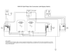
Issue #2 Neutral conflict between grid and off grid autotransformer. we are loading a schematic on this one: IF YOU ARE TAKING YOUR WHOLE HOUSE OFF GRID THERE SHOULD NEVER BE A NEUTRAL PASSED THROUGH FROM THE GRID. this is true for the split phase 12kW and 6kw inverters as well. the bottom line here is that all that is needed from the grid input is L1/L2. A dedicated ground rod is needed to bond to neutral of the off-grid autotransformer.

You can keep all of your grounds including the utility bonded, several big-name hybrids with transformers do this as well, like QCells, Delta and SolarEdge. If you are concerned about the boogeyman transformer mis-winding idea, then theoretically you could separate just the utility meter as in the below diagram (NOT REQUIRED/ THEORECTICAL)

As far as autotransformer size is concerned let's take a second and discuss what the ratings mean. the "imbalance power is reflective of the balance between the total 120v loaded L1 and L2 legs, NOT the total kW of 120v loads.

-Any 240v loads like an air conditioner, heater or pump pull evenly and therefore have ZERO load on the auotransformer

2x 5000es + 1 transformer with 5000w on L1 and 5000w on L2 has a transformer load of 0 watts, not 10000w,
5000W on L1 and 4000w on L2 is a load of 1000W on the transformer, not 9000w
-A 5000es + 1 transformer with 3kw of imbalance can run a max power split of 4kw/1kw on L1/L2
-2x5000es + 1 transformer can split max at 3.5kw/6.5 on L1/L2

This beats the imbalance tolerance of sol-ark, MPP, Growatt LF and most others, that's why this autotransformer has become a common trick by the Sol-Ark clientele

You can't run an unlimited amount with 1 transformer and per the manufacturer you need breaker protection, if you combine your inverters, transformers and 240v loads on the ac out panel and then feed your 120v loads panel you will be able to achieve full protection (VIDEO COMING)

If you have more than 5kw of 120v then odds are you need a second transformer.

Most off-grid folks have the 120v loads under control because they plan their lifestyle before going of grid. This design is a huge win on cost because the major off grid loads, like AC, Dryers, Ovens, and other large 240v loads now only cost $900 for 5kw with a 6kw 450v solar charger built in that needs no combiner box.
1643328922308.png

1642534857790.png
 

Attachments

  • 5000 ES Split Phase Grid Connection with Bypass.pdf
    175.4 KB · Views: 232
Last edited:
Issue #2 Neutral conflict between grid and off grid autotransformer. we are loading a schematic on this one: THERE SHOULD NEVER BE A NEUTRAL PASSED THROUGH FROM THE GRID. this is true for the split phase 12kW and 6kw inverters as well. the bottom line here is that all that is needed from the grid input is L1/L2. a dedicated ground rod is needed to bond to neutral of the off-grid autotransformer as well.

Gotta see a schematic of this.

I think you will pass through ground connection from utility service entrance (which has L1, L2, N) at meter and main breaker panel. A ground rod at the service entrance is used to ground the system, and bonds to neutral typically at the main panel.

You now feed L1, L2, ground, but not neutral to your inverter, which is not transformer isolated.
You add a transformer (is that auto-transformer, not isolated?) to establish a neutral after the inverter. You bond that neutral to ground.

First concern I have is, passing through all the power you can from grid, is customer limited regarding how much the can imbalance the two 120V phases? I think your transformer has to handle 100% of that imbalance.

Now about "THERE SHOULD NEVER BE A NEUTRAL PASSED THROUGH FROM THE GRID"
If I understand this circuit correctly, you are now passing neutral through. You're just using the ground wire to do so (and it is likely undersize, as ground normally is, for continuous current.)

We don't bond neutral to ground in more than one place because we don't want neutral currents to flow in ground. But I think this configuration would do just that (when grid feeds an imbalanced load on output of inverter.)

Schematic, please?
(ideally showing what relays are inside the inverter between grid on input side and loads on output side.)
 
schematic coming:
we said no neutral pass through and a dedicated ground, btw, this is the same instruction for the growatt LF split phase and the MPP split phase 6048
 
schematic coming:
we said no neutral pass through and a dedicated ground, btw, this is the same instruction for the growatt LF split phase and the MPP split phase 6048
so l1/2 from grid, then an independent ground rod?

output ground goes where? to CL panel?
 
So one ground rod for your service meter from the utility and another ground rod for the growatt system?

Or do you tie to one ground rod?
 
Gotta see a schematic of this.

I think you will pass through ground connection from utility service entrance (which has L1, L2, N) at meter and main breaker panel. A ground rod at the service entrance is used to ground the system, and bonds to neutral typically at the main panel.

You now feed L1, L2, ground, but not neutral to your inverter, which is not transformer isolated.
You add a transformer (is that auto-transformer, not isolated?) to establish a neutral after the inverter. You bond that neutral to ground.

First concern I have is, passing through all the power you can from grid, is customer limited regarding how much the can imbalance the two 120V phases? I think your transformer has to handle 100% of that imbalance.

Now about "THERE SHOULD NEVER BE A NEUTRAL PASSED THROUGH FROM THE GRID"
If I understand this circuit correctly, you are now passing neutral through. You're just using the ground wire to do so (and it is likely undersize, as ground normally is, for continuous current.)

Which is a violation, any grounding conductor can not pass current.
We don't bond neutral to ground in more than one place because we don't want neutral currents to flow in ground. But I think this configuration would do just that (when grid feeds an imbalanced load on output of inverter.)

Correct.

Schematic, please?
(ideally showing what relays are inside the inverter between grid on input side and loads on output side.)
 
I look forward to seeing the schematic, and a block diagram of the inverter would be great too.

What is the time frame on releasing these?
 
the bottom line here is that all that is needed from the grid input is L1/L2. a dedicated ground rod is needed to bond to neutral of the off-grid autotransformer as well.
This is the most terrible advice I have ever seen. I am sorry to say you guys have not the faintest clue about mains electricity and it's use and how the average Joe will try to use these things.
No one, but absolutely on one is going to drive a new 8 food ground rod just to use their transformer hacked non USA appropriate inverter.
 
The only SAFE way to use this inverter in the USA is to use an isolating transformer on the output (240 - 240/120) and a suitable breaker feeding it the 240v.
Also the incoming utility ground should be connected to the inverter input.
Now that ground seems like it should also be connected the the center tap (neutral/ground) of the output as per standard USA accepted and approved practice, BUT I AM NOT SURE.
 
Driving an 8' ground rod is no big deal, a normal part of some electrical work. I did that when doing a permitted and inspected install of a couple 2500W grid-tie inverters years ago.

Yes, isolation transformer with 120/240V split-phase output would work. I think center tap could either have its own ground rod, isolated from house, or use house's ground system. Or an additional rod and tie to house's ground. Whichever ground was used for the neutral (center tap) bond would also be ground for downstream circuits.

Isolation transformer means no galvanic connection to grid power, and no ground currents produced (except caused by capacitive coupling, typically a few mA.)

I think 240V inverter (across L1/L2) with an autotransformer could be used safely with centertap (which creates neutral) tied in to neutral of house, and ground tied in to ground of the house. What one needs to ensure is that autotransformer doesn't overheat, and if it is disconnected by a breaker, the loads must be disconnected too. (Don't want single-phase loads getting power from L1 or L2 to rely on N when N is no longer defined by the transformer.)
We drive ground rods because we are electrical engineers who give a crap, Joe blow turning all green to save the earth on the cheap ain't going to. Nor the guy living on rock ledge lol.
Single phase loads will not get power and be subject to possible loss of neutral and hence unbalanced 120v legs that will blow them up if the circuit breaker kills the voltage to the primary of the transformer.
 
We kind of have 2 separate issues going on here, grounding of electrical equipment when housed in a metal enclosure and the danger of loss of neutral to 120v equipment. It becomes the same problem here in the USA because of the effed up split phase system with ground tied center tap.
It is not an easy problem to solve as many heated discussions on the interwebs can attest to.
 
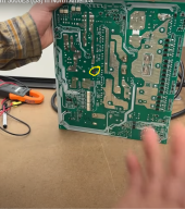
Has anyone confirmed yet on the Growatt 5k (by taking the board all the way out to see the stand-off underneath), and confirm if removal of the bonding screw is sufficient means of separating the bond? Or like is it a millimeter away from touching (like a light press on the board will make it connect again)? It seems to me if I was removing the bond, I would take the board all the way out for a minute and take off the standoff underneath it to confirm a safer separation distance.

Is this an issue? Pictures?
 
Last edited:
Sam this has not been done pubically yet.
The standoff/mounting post is pressed/welded into the case of the inverter, getting it out is no trivial matter.
And you have a heavy circuit board now missing a mounting point, not good for it's long term reliability.
Again, the manufacturer has done all this design and manufacturing for a reason, not just to make more work and less profit.
 
If you use a transformer like the following.

HAMMOND SG3N0037LE D16 SNTL-G3 1PH 37.5KVA 240X480-120/240V AL 60HZ 150C 3R

(BTW there are smaller versions of this transformer)

It will provide the isolation required and eliminate the need for the neutral forming transformer as well as any loss of neutral protection.

Its an expensive solution but simple and clean (KISS). Less parts less to fail.

I'd have to run the numbers but your inrush current may be high to initially energize the transformer.
 
This is the most terrible advice I have ever seen. I am sorry to say you guys have not the faintest clue about mains electricity and it's use and how the average Joe will try to use these things.
No one, but absolutely on one is going to drive a new 8 food ground rod just to use their transformer hacked non USA appropriate inverter.
Please familiarize yourself with dedicated grounds, they are used in many other aspects of solar installs. If you are an off grid user you are installing your own ground rod anyway. I'm sorry you've worked yourself up here but it is a $16 part and lowe's/ every other hardware store carry bundles on hand.

You're just plain wrong here sir.
 
Hello, we have reviewed Ian's video and discussed our approach with him, we wanted to start a thread discussing a completely safe way to operate the 5000ES and transformer.

Issue #1: neutral-ground bonding, we have had these units ship without the neutral to ground bond since we started carrying them in order to avoid issue 1 entirely, Ian is aware, and we agreed the real exposure here is the people buying direct from China with no thought to modification.
OEM modification specifically for the American market, they even designed the auto transformer for it to go with.

Issue #2 Neutral conflict between grid and off grid autotransformer. we are loading a schematic on this one: THERE SHOULD NEVER BE A NEUTRAL PASSED THROUGH FROM THE GRID. this is true for the split phase 12kW and 6kw inverters as well. the bottom line here is that all that is needed from the grid input is L1/L2. a dedicated ground rod is needed to bond to neutral of the off-grid autotransformer as well.

As far as autotransformer size is concerned let's take a second and discuss what the ratings mean. the "imbalance power is reflective of the balance between the total 120v loaded L1 and L2 legs, NOT the total kW of 120v loads, 2x 5000es + 1 transformer with 5000w on L1 and 5000w on L2 has a transformer load of 0 watts, 5000 on L1 and 4000w on L2 is a load of 1000W on the transformer.
-A 5000es + 1 transformer with 3kw of imbalance can run a max power split of 4kw/1kw on L1/L2 4
-2x5000es + 1 transformer can split max at 3.5kw/6.5
This beats the imbalance tolerance of sol-ark, MPP, Growatt LF and most others.
-Any 240v loads like an air conditioner, heater or pump pull evenly and therefore reduce the potential for imbalance.

You can't run an unlimited amount with 1 transformer and per the manufacturer you need breaker protection, but if you are building large system, odds are you have a lot of 240v loads that by nature will never touch the transformer at all. the inverter will trip pretty rapidly after, but your devices are partially exposed, however we have never seen an issue from people who put max 2 inverters per transformer.
Are we only talking about the Growatt European models only?
 
Back
Top