diy solar

diy solar

About to spend a lot of money tomorrow on this system (am I making a mistake?)

The autotransformer provides the split phase. The question is do you do it at location A and send split phase to B & C, or do you send single phase from A to autotransformers to B & C.
Part of that question should be, why have auto transformers at all?
If the un-balanced current is low enough that voltage drop is within spec on the neutral then no transformers are required.
I'm sure you know this but for those who don't...
If the load on L1 is 10A@120VAC and the load on L2 is 5A@120VAC then the neutral only carries the 5 amp imbalance.
Voltage drop is about distance, voltage and current.

On the other hand, maybe its worth while to step up the voltage to 480VAC for distribution and step it back down at the remote buildings.
Then treat each panel as a main panel with its own neutral/ground bond and earthing.
 
Last edited:
Part of that question should be, why have auto transformers at all?
If the un-balanced current is low enough that voltage drop is within spec on the neutral then no transformers are required.
I'm sure you know this but for those who don't...
If the load on L1 is 10A@120VAC and the load on L2 is 5A@120VAC then the neutral only carries the 5 amp imbalance.
Voltage drop is about distance, voltage and current.

On the other hand, maybe its worth while to step up the voltage to 480VAC for distribution and step it back down at the remote buildings.
Then treat each panel as a main panel with its own neutral/ground bond and earthing.
I have zero idea about any of this but I do wonder if it's determined I need to have a transformer step it up to 480V or higher, and then another transformer to step it back down at the cabin, do I need to have an auto transformer?
Every transformer comes with power loss so I'd like to avoid them, but I don't even know how to calculate wire size or wire sizes based on this new apparent need to have 2 or 4 wires or whatever.

If an isolation transformer has 120/240V primary and 120/240V secondary, it could be wired with all windings in series: 120+120+120+120
Center tap grounded, inverter feeding the 120+120 pair in the middle. That makes an auto-transformer to form grounded neutral. Outer pair of wires are each 240V, so 480V can be transmitted to distant site with 1/4 the loss (and/or smaller gauge wire). Perhaps neutral wire should be routed too, when not using as isolation transformer. At least if center grounded and 120V loads are present at one end, can cause voltage imbalance.

Transformers are wound with secondary having about 5% extra turns. Output voltage is 5% high under no-load, 5% low under full load.
The other 120+120+120+120 configured transformer might have order of primary/secondary series connection reversed, because it is used for step-down rather than step up. Would end up delivering 10% high voltage no-load, 10% low full load.

A higher wattage (VA) rated transformer wouldn't have as much voltage sag. Some have multiple taps to adjust voltage a few percent.

Toroid transformers are more efficient, not as readily available. They draw a larger momentary surge current when first connected, which could be a problem. Conventional "E" core transformers are readily available second-hand. Autotransformers are more efficient and can be less expensive, because only half the power is actually coupled by them (for a 2x or 0.5x voltage conversion.)
 
As to the wire sizing, my dealer says:

You're looking at around 2awg. The 8k would only be able to output around 35A. 2 awg would be a 2.7% drop at 240. The 120v legs are 2/0 so that's a problem.
If it was me I would put the auto transformer in the house, limit your current, wire size and an extra wire. Might run a 3rd wire just for future proofing.
Realistically you're not going to be running full power though your 120v legs anyways so you should be good.

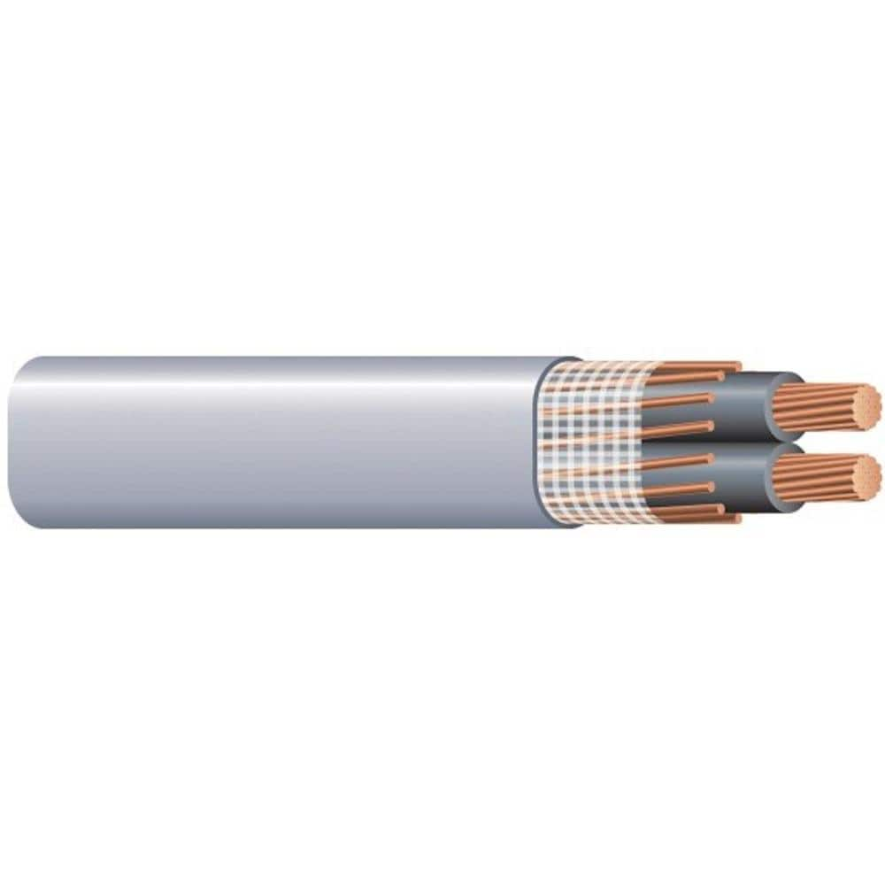
I don't know if this wire is the 2/0 that fits the bill, but if it is....expensive.

 
I'm going to look into moving my inverter, batteries, MPPTs, & auto transformer half way between the PV and the Location B cabin.

That would be 250' of DC wire from the PV to the MPPTs/inverter/etc and then 250' of AC wire(s) to the cabin.

But since I can't understand let alone calculate wire sizing for the AC wire(s), I don't even know beyond intuitive feel whether or not this would save money.
 
$13/foot.
Two lines and ground, no separate neutral. I think that can be used with transformer-isolated circuit, but think there might be a problem with auto-transformers at two separate locations, each using a grounded neutral. (But is that what our neighborhoods are like, when multiple houses are fed from a single transformer on utility pole?)

Inverter half as far away cuts losses in AC wire in half. Increases PV DC losses. If PV is higher voltage, that's better. If PV wire is smaller gauge, that's worse. If PV delivers power 12 hours per day and inverter delivers AC at constant power 24 hours per day, higher power shorter time in PV is worse. If AC has surges to high power, short AC wire is better.

Running double voltage cuts losses to 1/4 as much. Or, you can use wire with 1/4 the cross section, 1/4 the price. Plastic insulation is cheap, copper is expensive. Isolation transformer, 120/240V on one side, 480V on the other, could be the way to go. Maybe even higher voltage, depending on exact peak or RMS voltage rating of insulation. (480V if center tap grounded is only 240V RMS on each lead.)
 
Every transformer comes with power loss so I'd like to avoid them, but I don't even know how to calculate wire size or wire sizes based on this new apparent need to have 2 or 4 wires or whatever.
The 4 wires are L1, L2, N and G.
The N is 120 volts and will probably only ever see 12 amps or less.
Its just another item to check separate to the 240 volt calculation.

To give an example with nice round numbers.
Lets say the max continuous load 240 volt we are expecting is 50 amps and 500 feet.
To get under 3% voltage drop requires 3/0 awg aluminum for the current carrying conductors.

This is the wire I propose

For 3/0 aluminum

For 1/0 awg copper

The 120VAC load on the neutral should not exceed 12 amps which means the voltage drop is well within spec.
For aluminum 3/0 aluminum

For 1/0 copper

If anyone sees a fault with my calculations please educate me.
Also I've been fasting for ~66 hours so I'm a bit punchy. ?
That's awesome that it shows your work. Thank you for that. I'll study this and see if I can understand it. Much appreciated.
 
If it ever matters, the GX device has a function called DVCC. It allows the GX to manage additional stuff. Let's say for some reason, you wanted to restrict battery charging current to 300A. DVCC allows you to enter that limit.

It will limit charging from all GX connected sources to the 300A specified, but if your loads demand more, and the array can deliver it, the array will produce it.
Part of that question should be, why have auto transformers at all?

Because his inverter will not provide split phase. It has L and N with 230V between. No 120V.

On the other hand, maybe its worth while to step up the voltage to 480VAC for distribution and step it back down at the remote buildings.
Then treat each panel as a main panel with its own neutral/ground bond and earthing.

Can't disagree. It's a numbers game. $ for transformer with thin wire or $ for thick wires. At 800', it might pay for itself.
 
get some No Salt, some salt and some MaCl into you now! Stopping at 72 or longer?
Just had 30ml ACV with 2.5ml No Salt plus other fortifications.
Was going for 96 but the wheels are falling off, probably going to stop at 72.
My arms, legs and brain are at cross-purposes right now.

Do you mean NaCl?
 
Just had 30ml ACV with 2.5ml No Salt plus other fortifications.
Was going for 96 but the wheels are falling off, probably going to stop at 72.
My arms, legs and brain are at cross-purposes right now.

Do you mean NaCl?
Crap, no I meant MgCl.
 
@AlaskanNoob why are you running a euro-centric inverter and presumably a euro-centric inverter-generator?
Unless you have some 230VAC@50hz loads I think it is just unnecessarily complicating things.
I chose Victron because I like how it works together and it gets great reviews. So endeth my thought process on that particular decision.

Our cabin has a 230V load with the ClimateMaster Trilogy 45 Q-Series 2-ton heat pump.
 
I chose Victron because I like how it works together and it gets great reviews. So endeth my thought process on that particular decision.

Our cabin has a 230V load with the ClimateMaster Trilogy 45 Q-Series 2-ton heat pump.
What I mean is it generates simple 230VAC@50hz and we want 120/230VAC@60hz split phase for distribution and consumption.
Victron makes inverters that support 120/240VAC@60hz for the North American market.
I very glad I asked, this will remove a lot of jiggery-pokery from the system even if we go with transformers.
We really should have started here.

Do you have a power budget for each of the buildings?
By that I mean peak instantaneous power in kilo-watts and kilo-watt hours per day?
Can you make an itemized list of the 120 and 240 loads?
 
Back
Top