diy solar

diy solar

Growatt SPF5000ES doesn't trip RCD in batterymode

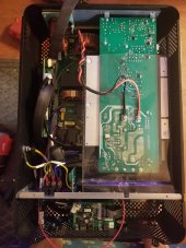
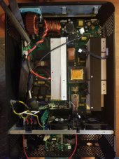
So I've put back the earthing screws. Without these screws an RCD can be put before the inverters, it will never trip the rcd unless there is an actual fault to ground when on grid -- but not when you're off grid, it'll just keep on trucking.
When you have these screws out and you want to trip the rcd's downstream of the inverters (typically those rcd's are placed in the distribution panel) while you run offgrid you need to tie the neutral to ground before it enters the first rcd. That will trip the rcd's downstream in offgrid. However that will only work in offgrid for my situation because the second you go ongrid the rcd upstream will trip, rightly so.

The only solution to keep it safe is to put back the grounding screws and remove the rcd upstream because it will just fault every time the inverters detect the grid and switch the relay. -- the relay is a 1000 times slower than the rcd.
So no fault current can be detected between the main panel and ac out of the inverter. The inverter is still grounded correctly --so nothing trop funky can happen.
The rcd's downstream now keep working no matter if the inverters are on or offgrid.

Still irks me that I have no ground fault detection between the main panel and the inverter other than a 40A breaker.
 
Last edited:
That's probably as good as it's going to get. Without a neutral supplied from the utility. The main thing is that you are protecting the dangers from human touch. Upstream of the inverter should only be touched by qualified people. And, they know to be cautious.
 
Not having a neutral is just insane. You know why they decided to do that back in the day? To save on copper by not having to string a fourth wire carrying neutral.
In 2022, with electronics getting more sophisticated that will bite me in the ass at some point. (Electric car chargers in particular)

There's an idea, I could install an isolation transformer and transform this delta in a true star with center tapped earth coming straight from my very own earth pin. Not very efficient, mind. There's at least a 3% loss.
 
I did actually play with this some more and I have some other observations.

So unmodified, no screws removed --totally stock, I can switch from battery to utility if I disconnect the grounding of the growatts during the change over. After the changeover, when it is in bypass, the grounding can be reconnected, it will not trip the upstream RCD.

I've spent some time with these inverters and I know that every time there's a change in the supply side it will beep at ya. So if you instruct it to switch from utility to solar , or from solar to utility or battery, or whatever, -it beeps.
But more importantly, it beeps before it takes action and it keeps beeping until it completed the action.

You catch my drift?
 
I have accessed the change over relay circuit. To control the n/g issue for use in the US.
It provides 230v when in battery mode.
 
Hm,.. could I do something with that, where is that located on the board?
 
The ground screw location. In battery mode, there's 230v from that spot to L.
 
Hmm. I had a quick look when I switched the inverters off while I was running a fatter battery cable to the inverters but I could not find that buzzer. At least it is not immediately visible when you take the covers off. I suppose it will be on that tall board that is stuck to the heatsink, but on the side facing inwards.

I'll have to look at it when I can afford a longer downtime altough I do have two of them so I could run it in in single mode while the other one is on the healing bench.
 
I have pictures of the boards, from when I had mine apart. I'll see if I can spot it.
 
Oh that would be excellent even for reference later on, you should totally post those.
If you can't find them I could also do it when I tackle this tomorrow or whenever I find the time to mod the inverter.
 
Here
 

Attachments

  • 20220222_095657.jpg
    20220222_095657.jpg
    178.3 KB · Views: 27
  • 20220222_092337.jpg
    20220222_092337.jpg
    153.4 KB · Views: 25
  • 20220221_222305.jpg
    20220221_222305.jpg
    143.7 KB · Views: 27
  • 20220222_090258.jpg
    20220222_090258.jpg
    153.6 KB · Views: 24
  • 20220221_222248.jpg
    20220221_222248.jpg
    151.4 KB · Views: 23
Yeh .. I cannot spot it either. It could very well be hiding in the display unit.
I'll try to pin point it tomorrow, I'll disconnect one of the growatts and try to find it by ear. Having two of them makes it difficult to home in on the location of the buzzer since they but start to beep when I switch them on.

If I find it I have everything I need, I just need to fabricoble a nodemcu that'll watch the voltage on the beeper line and I can switch an earthing box with that. The nodemcu can live in the growatt and get 5v from the usb connector.
 
Surprisingly, it's not very crowded inside the case. Which is great for air circulation. That's probably why they never get more than luke warm.
 
Based on your grid voltage measurements, I think your utility secondary is a wye (star) rather than a delta. The utility does not supply a neutral because you have no need for 132 volts. In a wye configuration, voltage from any phase to neutral (ground in this case) is phase-to-phase voltage divided by 1.73, which matches your measurements. 230 / 1.73 = 132.9

I have a hunch there are two relays in the inverter, one to switch from grid to battery (relay 1) and the other to bond (ground) the neutral (relay 2). I think that relay 1 opens and closes before relay 2.

Switch to Battery
  1. Relay 1 closes
  2. Relay 2 closes
This works OK because the AC In neutral is disconnected by relay 1 from the grid (H3) before relay 2 bonds the neutral.

Switch to Grid
  1. Relay 1 opens
  2. Relay 2 opens
This does not work OK because relay 1 connects the AC In neutral to the grid (H3) before relay 2 un-bonds the neutral and for a very short time the grid (H3) is shorted to ground and trips the RCD (I didn't draw it) that is between the grid and the inverter. That is why the RCD does not trip if you disconnect the inverter ground before the switch to grid and then reconnect it after the switch to grid.


I read about RCDs that have a time delay before they trip so maybe that would be a solution that would be slightly better than just a regular breaker.

inverter.png
 
Small controller board (with B written on top of the inductor) in picture #3 is where I think where the buzzer is, it is a small black round device with small hole on top, it is to the left of the third multi-pin black header counting from the top right of the picture, to the left of the buzzer is a small lytics cap, and below the cap and the buzzer is the Xtal.
 
Small controller board (with B written on top of the inductor) in picture #3 is where I think where the buzzer is, it is a small black round device with small hole on top, it is to the left of the third multi-pin black header counting from the top right of the picture, to the left of the buzzer is a small lytics cap, and below the cap and the buzzer is the Xtal.
Yup
That could be it.
That board is on the left side of the inverter.
Against the side wall.
Plugged into the main board.
Very easy to access.
It's actually upside down in the picture.
 
@mccljs : You are correct, it's not grounded to a phase but in the center, it's a star. Nice visualization and great first post.
@Bud Martin : Looks like you might have spotted it, I'll confirm later today.

I found a manual for the SPF5000ES in another forum which differs from my manual, the dry contact has different criteria to switch via a setting 24. It's located here https://solaradvice.co.za/wp-content/uploads/2021/01/User-Manual_Growatt-SPF5000-ES_2020_ENG.pdf

My manual has none of that, it switches the dry contact based upon battery condition.
 
Back
Top