diy solar

diy solar

Mixing LF280N(2x4s1p) with LF280K(2x4s1p) in series for 48V?

Islander_00

New Member
Joined
Nov 4, 2020
Messages
4
Location
Greece
Hello all,

I am refitting my sailboat (Moody 376) with all new DC & AC systems.

Last summer I ordered 8x LF280N cells to build a 24V (8s1p) battery to be used as a main house bank (Victron 24V Multiplus II 3KVA, DC-DC charger - all other systems on board will remain @12V).

As work got in the way, I used the multiplus on a different project and so I now only have the Cells which are brand new (1 Cycle for testing).

As I am now revisiting the sailboat project, It got in my head to switch to a 48V system as I will be looking into electrical propulsion sometime in the future (e.g. an epropulsion 48V 6KW installed in the back for maneuvering/motor sailing... or maybe two of them... but that is a conversation for another time).

I have quotes from reliable vendors through alibaba for LF280N/K cells which will take 2-3 months to arrive to Greece.

I also have a quote for LF280K cells that should be available in EU Warehouse in a few weeks so I could be getting them by the end of the month.


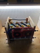
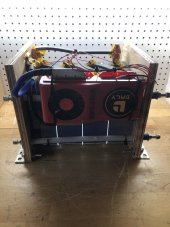
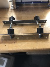
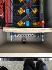
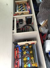
Also note that I have decided to split the cells in 4 custom battery boxes (4s1p) for easier handling. Each box will have a 9p waterproof connector for balancing leads and two posts (or 175A Anderson connectors or both... haven't decided yet) for main (-) & (+). Each series connection between the boxes will be by thick 75mm cable.
The BMS will be placed externaly (maybe in its own box?) and I am looking at the JK BMS which should talk to the Inverter - a 48V Multiplus II 3KVA unit.

so to put it in perspective:


Main Positive (+) ----| BAT_Box1 4s1p LF280N |--| BAT_Box2 4s1p LF280N |--| BAT_Box3 4s1p LF280K|--| BAT_Box4 4s1p LF280K|----JK BMS---- (-) Main Negative


Question is... should I mix 8xLF280N with 8xLF280K in series for 48V???
It will save about 1000$ at this time..

Thoughts on the above?


P.S. - Sorry for the long post...
 
Your "long post" provided excellent details. The higher quoted lifespan of the newer 'N'' cells might imply a change in anode design and construction. That could lead to differences cell resistance, and resistance of entire battery packs. But that could only matter in the case of parallel packs (e.g. 2 packs at 24V in a 24V system).

In your situation, all battery cells are in series. The full amount of current MUST be pushed/pulled through all cells, without regard to individual cell resistance. So mixing creates no problem at all, you could even mix cell types within each of your individual boxes.

However - as has been WIDELY discussed on this forum (in numerous large threads), EVE themselves tested the lifespan of some earlier model cells (I can't recall of they were "L" or "K"), and found great benefits in total lifespan from compressing them. A lot, well over 650 pounds on the faces of the cells being tested. (They used a big press in testing, while most of us use springs to construct such battery packs.) The 'N' cells, rated at 6000 cycles, might not need it. But compressing the K cells could do them a lot of good.

The issues for you, in considering that, are the increased size of the "K" packs (with rods and springs sticking out of one side), and the extra cost for two sets of "springs" and "compression plates". I understand that you might need to build '4s' boxes due to the total length. But if it can possibly fit, you could construct all of the 'K' cells into a single 8s pack, with only one pair of plates. I would assemble such a pack in place, right on the boat.
 
The issues for you, in considering that, are the increased size of the "K" packs (with rods and springs sticking out of one side), and the extra cost for two sets of "springs" and "compression plates". I understand that you might need to build '4s' boxes due to the total length. But if it can possibly fit, you could construct all of the 'K' cells into a single 8s pack, with only one pair of plates. I would assemble such a pack in place, right on the boat.
why not just discharge the batteries and build a hard box around them. They will naturally compress themselves, and you‘ll save room.
 
why not just discharge the batteries and build a hard box around them. They will naturally compress themselves, and you‘ll save room.
What kind of "hard box" is going to create almost 700 pounds of force on those cell faces? Like the notion of "I'll just tape them really tight", that's useless, unless some heavy-duty pressure pulls the two ends together. A REAL "compressed" 4S battery pack looks like this: gorgeous battery packs with compression.
 
Last edited:
I was thinking of using wood and fiberglass.
Nope. Some people have tried a similar combination (wood box with high-compression foam) and had poor results. Spring-Loaded is the most space-efficient method. The willingness of the compressed "end plates" is also a big issue. May people have had good results from 1" plywood with assistive metal crossbars spreading the load across the width, from the outside (see pictures within that Thread).

My plates are 1/4" steel (very space-efficient and resistive to bending, but much heavier than 1" plywood). Here's a just-finished 12v battery pack of EVE 230-N cells of mine, nearly ready to go into the RV Trailer. (it still needs a wood bottom-plate. I'll probably also add two thin wood "end plates", just to make it more pretty.) Within the RV battery enclosure, I'll probably be leaving it leave it "topless".

The "extra" screw length, allows for the pack to be de-compressed, if I ever need to replace a single failed cell. To prevent conductivity through the cell side walls, I have thin plastic plates between cells on the inside, and a few layers of "contractor's trash bag" between the end cells and the adjacent steel plates. (Eve cells are insulated from the factory, but the insulation layer is very thin - and the casing is conductive aluminum. Each cell is charged to a different ground potential, so they must not be allowed to contact each other through scratches).
 

Attachments

  • Eve-230-compressed.jpg
    Eve-230-compressed.jpg
    480.9 KB · Views: 12
Last edited:
Before you build a complicated compression box in the limited space of a sailboat, you might want to actually calculate the actual full, 100->0 equivalent, cycles you might get in a year. In my experience, 40’ sail, the actual number is quite low. The loads are mostly low or intermittent, and charging is regular - solar and occasional motoring, thus the battery happily “cycles” slightly in the middle of the SOC range. Once you get over the lead acid mentality of “must keep it full”, life is much easier. So… the increase in cycle life from compression for shallowly cycled batteries becomes relatively unimportant. My batteries will die from calendar aging long before they suffer from compression effects.
 
Nope. Some people have tried a similar combination (wood box with high-compression foam) and had poor results. Spring-Loaded is the most space-effiicient method. The willingness of the compressed "end plates" is also a big issue. May people have had good results from 1" plywood with assistive metal crossbars spreading the load across the width, from the outside (see pictures within that Thread).
I’m not sure how you make the leap from a wood/fiberglass composite to wood/high compression foam.
And what do you mean “poor results“? The design you linked to previously, looks like a wood/carbon fiber composite.

That thin trash bag isn’t really a great insulator. At the voltages of these cells, you’re probably fine for a while, but eventually the vibration will wear through it.
 
Last edited:
I’m sure how you make the leap from a wood/fiberglass composite to wood/high compression foam.
and what do you mean “poor results“?
The mere box, without compression rods and assistive 1" square bar to spread the load onto the full width of the target faces, simply warped after it's "compressed assembly". I don't have a link to that particular attempt, but I think that it had an entire Thread dedicated to the concept ("search" is your friend, if you want all the gory details and subsequent rock-throwing).
 
The mere box, without compression rods and assistive 1" square bar to spread the load onto the full width of the target faces, simply warped after it's "compressed assembly". I don't have a link to that particular attempt, but I think that it had an entire Thread dedicated to the concept ("search" is your friend, if you want all the gory details and subsequent rock-throwing).
The box you linked to above shows wood/carbon fiber, held together with steel rods And not square bar. Is that the one that warped?
 
Before you build a complicated compression box in the limited space of a sailboat, you might want to actually calculate the actual full, 100->0 equivalent, cycles you might get in a year. In my experience, 40’ sail, the actual number is quite low. The loads are mostly low or intermittent, and charging is regular - solar and occasional motoring, thus the battery happily “cycles” slightly in the middle of the SOC range. Once you get over the lead acid mentality of “must keep it full”, life is much easier. So… the increase in cycle life from compression for shallowly cycled batteries becomes relatively unimportant. My batteries will die from calendar aging long before they suffer from compression effects.
Thanks, this was an excellent point! his usage of the boat might not involve as many discharge/recharge cycles to make any difference. (The lifespan of uncompressed "K" cells, taken from 100% to near "zero" within EVE's test, was about 2000 high-stress cycles. Compression improved that by a factor of 3x.) LFPs definitely prefer to be stored at low SOC, I've been keeping my RV Trailer batteries at about 35% through the winter.
 
The box you linked to above shows wood/carbon fiber, held together with steel rods And not square bar. Is that the one that warped?
His battery IIRC, used 1" plywood. I don't think that he added anything to spread the loads better, but it's probably adequate. It is certainly pretty, and that's the main reason I referenced his photo. :LOL:
 
A boat takes a lot of pounding, I would clamp them to keep them from moving around and messing with your cell connections. I am doing a mobile application in a truck that goes off road for work and decide to make the compression fixture mount on rubber vibration dampers. The other reason is I will have a total of 16 12 volt 280ah batteries, two in the truck two in the truck camper and twelve at the homestead they will all be inter changeable for redundancy.
 

Attachments

  • 05EBB28E-CBEB-421B-8716-18C94177929E.jpeg
    05EBB28E-CBEB-421B-8716-18C94177929E.jpeg
    128.4 KB · Views: 10
  • 7481F107-49F0-4DC6-9E92-2CDCB72D134E.jpeg
    7481F107-49F0-4DC6-9E92-2CDCB72D134E.jpeg
    131.5 KB · Views: 10
  • A9FC7AD9-00D7-48FD-8933-18FCEF0A884E.jpeg
    A9FC7AD9-00D7-48FD-8933-18FCEF0A884E.jpeg
    125.3 KB · Views: 10
  • 4A3C58CD-8CAD-4920-8A19-AEC0CD7D710F.jpeg
    4A3C58CD-8CAD-4920-8A19-AEC0CD7D710F.jpeg
    160.8 KB · Views: 10
  • 5BEFE5F5-7903-49A1-AA39-E3E718899BE6.jpeg
    5BEFE5F5-7903-49A1-AA39-E3E718899BE6.jpeg
    169.3 KB · Views: 10
Wow.. great feedback from everyone!

So I guess I will be ordering the 8pcs of LF280K cells at this time, saving some $$.


As far as compression is concerned, I was thinking of a middle ground between an elaborate construction and a basic arrangement that would guarantee some compression but mainly minimize movement in a boat environment.

Each 4 set of cells will have 1mm plastic sheet (chopping mat) insulation between them and two thick PTFE plates (2cm thick) at the ends with stainless rods keeping the whole thing together.

Something like this:
cell_compression.png

Torque specifications could be just to the point of cells staying in place when depleted and compressing themselves as they expand by getting full… (open to discussion on the merit of this argument though..)

Each of the 4 sets will be bolted inside a wooden frame epoxied inside of a long settee. I will probably add an acrylic top just for ease of inspection. Also the use of rubber vibration damper mounts as S Davis suggests sounds like a great idea!!

That should make each box about 40cm long x 30cm high by 25cm deep so 4 boxes would fit nicely inside a 210cm long settee with adequate space for cable runs..


As an afterthought I will probably add a single 4S bms (JBD-4S 100A) in each box just as a way to be able to draw 12V from each battery (for critical systems - just in case) or even 48V in series for redundancy if the JK BMS quits on me (A spare of each BMS should be on board as well..).

This will also add the ability to monitor temperature of the cells in each set.

...another long post (excited much? :ROFLMAO:)

Any thoughts welcome!
 
Wow.. great feedback from everyone!

So I guess I will be ordering the 8pcs of LF280K cells at this time, saving some $$.


As far as compression is concerned, I was thinking of a middle ground between an elaborate construction and a basic arrangement that would guarantee some compression but mainly minimize movement in a boat environment.

Each 4 set of cells will have 1mm plastic sheet (chopping mat) insulation between them and two thick PTFE plates (2cm thick) at the ends with stainless rods keeping the whole thing together.

Something like this:
View attachment 89848

Torque specifications could be just to the point of cells staying in place when depleted and compressing themselves as they expand by getting full… (open to discussion on the merit of this argument though..)

Any thoughts welcome!
I think that your photo has 90% of the work done, but very little compression benefit obtained. If the cells expand when highly charged, the fixed length of the stainless rods could cause excessive compression when they expand - or no compression at all if they shrink. (No compression at all would allow the pack to fall apart.) Compare my photo (within post #6) to the one you have here, but ignore the presence of BMS and fuse holder in my photo: They're nearly identical. I merely skipped the L-channels, because my steel plates are strong enough to handle the pressure from the spring ends without assistance from washers or load-spreading bars.

Looks great! Your "L" channels segments do a decent job of spread the pressure across the plastic plates. You need only lengthen the rods by about 1-1/2" on one side (and the L-channel already consumed 1" of that length), and the springs and a washer to each of your 4 threaded rod ends. The springs sit on top of the L-channel rod holes (using the L-channel itself as the lower washers, with just the spring, washer and nut above each of the L-channel rod holes.

You'd want to go with SS springs, they're more expensive - but nothing in comparison to the batteries themselves. But also remember the excellent post #7 from codfish: Instead of high-powered compression springs, you could go with smaller springs (shorter, less powerful, and cheaper) to merely assure that the pack holds together when the cells shrink a bit. During compression (cell expansion) the little springs would simply "bottom out" and leave you in the same situation as your photo. You wouldn't achieve the additional lifespan in 'maximum cycles', but you might not need it - and the smaller springs save an inch or so, on the length of rods.
 
As an afterthought I will probably add a single 4S bms (JBD-4S 100A) in each box just as a way to be able to draw 12V from each battery (for critical systems - just in case) or even 48V in series for redundancy if the JK BMS quits on me (A spare of each BMS should be on board as well..).

This will also add the ability to monitor temperature of the cells in each set.

...another long post (excited much? :ROFLMAO:)

Any thoughts welcome!
This part confused me.

Without pretty drastic re-wiring, only the first of your 4 battery packs would provide usable "12V" in an emergency situation. The others (all in series) would have higher "ground" terminal potential of "12v", "24v" and "36v" each. (Each adds another 12v, and their ground must not be used with chassis ZERO-grounded boat equipment.) That first cell could be built with another connector on the 4th cell "+" terminal (one leading to the second pack, the new "emergency" connector providing 12V).

You could, however, build each as a single 4S pack with that "12v" BMS unit - and carry just ONE spare BMS (with all the tools to install it) as the back up for all of them. To see the full Voltage of your 16S set, you'd use a different monitor - but you really need another coulomb counter monitor anyway, because some BMS units do not really report a very good value for SOC anyway (they measure only voltage, and do not actually count "coulombs").

Cell balancing would occur only within a pack (and not "across all cells") but that should be an insignificant factor when all the cells have the same capacity, without a "weak cell" running away with high voltage after becoming full "too early" in comparison to others.
- - -
You could also wire your 4S "packs" as 2S-2P, using 8S "24v" BMS units. Your first single pack could still have an "emergency 12V lead" attached to its 4th cell, even though the pack is wired with another for BMS purposes. In emergency use, full current would be shown on the BMS monitor, but only the first 4 cells would be used - And you would see their voltage being dragged down, while the 2nd 4 cells would remain at constant voltage.

@rickst29 thanks for your comments! I will definitely look into adding the springs for light compression...

As far as tapping 12V from the 48V bank I was thinking something like the following:

48v-12V_01.jpg
Would that even feasible...? If yes it would provide up to 120A @ 13.8V DC to the 12V bus bar so it could run the hole house electronics and provide floating charge to the starting and windlass batteries..

Or maybe I am just over complicating things...

-EDIT-

Just remembered that DC-DC Converters (thinking Victron Orion) will not do step-up so the actual output should be at nominal (4S) 12.8V DC. ...but still...
 
Last edited:
Now I understand. That works, as long as you "break before make" on the "-" terminals of three out of 4 (not the one on the right). The "last" pack on the left must be disconnected from the "+48" V charger connection (switch not shown in your picture), and those 3 packs must be all disconnected from each other before connecting to common ground.

You can use 2-battery 3-way switches for the 8 cut-over jobs, but the switches must be 3-way "Bat-1" or "OFF" or "Bat-2", in order to enforce the totally "OFF" position (for each of the 4 packs) before engaging the "12V" ground and hot connections.

Will a 4S JBD unit automatically activate, even with no charge voltage present, when the 12V connections are made? My DALY BMS devices won't do that; you must either apply a charging voltage to the battery pack; or use the DALY 'light board' activation button; or use a different switch to create a momentary short-circuit across the light board "activation" pins of the BMS (imitating the light board button).
 
Back
Top