Since I am such a NEWBIE, please help give me confidence this won't blow up on me, I welcome your thoughts and suggestions.
This system will be in a minivan.
206ah battery
Cables 2/0. 4' round trip to/from busbars.
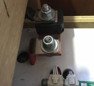
Fuse 225-amp battery mounted thermal fuse block.
Inverter 220 watt.
Cables 2/0. 4' round trip to/from busbars.
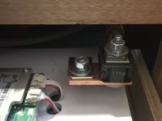
Fuse 200-amp mounted next to positive bus bar.
12v vehicle battery positive terminal to Victron 12/12-30
Cable #6, 4' long
Fuse 60-amp at 12v battery
Cables #6 to/from Victron. 14' round trip to/from busbars
Fuse 60-amp at positive bus bar.
DC fuse box, rated for 100-amp max
Cables #2. 4' round trip to/from bus bars
Fuse 125-amp at positive bus bar.
This system will be in a minivan.
206ah battery
Cables 2/0. 4' round trip to/from busbars.
Fuse 225-amp battery mounted thermal fuse block.
Inverter 220 watt.
Cables 2/0. 4' round trip to/from busbars.
Fuse 200-amp mounted next to positive bus bar.
12v vehicle battery positive terminal to Victron 12/12-30
Cable #6, 4' long
Fuse 60-amp at 12v battery
Cables #6 to/from Victron. 14' round trip to/from busbars
Fuse 60-amp at positive bus bar.
DC fuse box, rated for 100-amp max
Cables #2. 4' round trip to/from bus bars
Fuse 125-amp at positive bus bar.