diy solar

diy solar

Hacking the new Growatt WiFi-F modules

octal_ip

Solar Enthusiast
Joined
Jul 2, 2022
Messages
314
Hi all, just sharing my recent experience working with a Growatt SPF 3500 ES and the included WiFi-F module. I have a few other solar systems already feeding their data into InfluxDB and Grafana, and wanted the new Growatt unit to do the same.

Otti’s project on GitHub provided some inspiration, however the newer generation Wifi-F module proved to be a challenge to interface with. I spent quite a while trying to communicate with the ESP8266 using a few different serial adaptors (Silicon Labs, FTDI and CH340), however all attempts were failing very quickly with various serial communication errors.

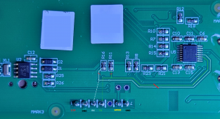
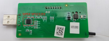
In the end I found that the SIPEX SP3232EE RS-232 transceiver on the rear of the PCB, which is also connected to the RX and TX pins of the ESP8266 was the culprit. As a workaround I tried interfacing with the SIPEX chip’s own RX and TX pins, however this didn’t work. The only solution I could find was to remove the chip from the board temporarily while I uploaded new firmware.

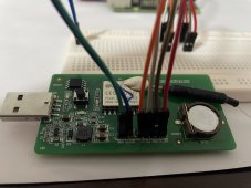
Once the SP3232 chip is removed, the ESP8266 is easy to work with. All the necessary pins (GND, TX, RX and GPIO-0) are broken out to a standard 0.1” through holes that a pin header can be soldered to. The chip can be placed in flash mode by shorting GPIO-0 to ground while it's reset.

I included OTA components in my firmware so any future updates could be done without a serial interface, then re-soldered the chip. From here everything worked perfectly.

Another note is that the board seems to be quite power hungry, I had it running from a good quality USB power bank, however it would reset itself during firmware updates. Powering it from a higher voltage source solved this issue. It has an onboard buck converter, so it's happy to accept well over 5v.

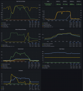
The end result was the Growatt reporting all its statistics into InfluxDB and Grafana, screenshots are attached. I’d be happy to upload my code to Github if anyone is interested.
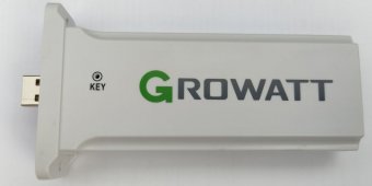
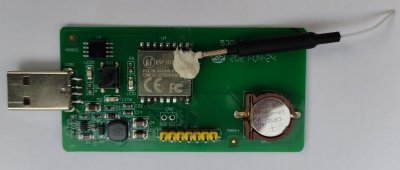
I’ve also attached photos of the WiFi-F unit and each side of its PCB.


Edit 30/09/2022:
Code and updated instructions posted to GitHub. It's possible to upload the new firmware without cutting traces or removing the SP3232 chip by using a Silicon Labs CP2102 USB to UART adaptor. These are unique in that they have strong enough drivers to overcome the impedance of the SP3232 while it's in place.


Attachments

  • Growatt Grafana.png
    Growatt Grafana.png
    345.9 KB · Views: 229
  • Wifi-F Case.jpg
    Wifi-F Case.jpg
    22.9 KB · Views: 222
  • WiFi-F PCB Bottom.jpg
    WiFi-F PCB Bottom.jpg
    97.5 KB · Views: 218
  • WiFi-F PCB Top.jpg
    WiFi-F PCB Top.jpg
    53.8 KB · Views: 240
Last edited:
Thank you for posting this. I also noted difficulty connecting to the esp chip, and have run it with stock firmware for a few days.

Today however my ISP is down, so I have no monitoring, and the shine tools are useless.. but as I already have home assistant and grafana locally for other uses I'd love to re-try going open source on my system.

I'll try lifting the pins or maybe cut the traces (reconnect them later) if possible and see if that works. I already have header pins soldered on the board.

Did you save off the stock firmware first?

Will post once I'm done. ;)
 
Yes, I dumped the stock firmware before I started experimenting with my own, I've attached it for whoever might want a copy.

I can also post all the MODBUS registers if it'd be helpful, through trial and error I found that the documentation for these systems has a couple mistakes and many registers that don't return anything useful.
 

Attachments

  • Growatt_Sunshine_flash_4M.bin.zip
    310.3 KB · Views: 208
Here's the list of working registers:

Name
Address Offset (from 0x1000)
Type
Multiplier
Unit
System Status​
0​
uint16_t​
1​
0: Standby;
1; (No Use);
2: Discharge;
3: Fault;
4: Flash;
5: PV charge;
6: AC charge;
7: Combine charge;
8: Combine charge and bypass;
9: PV charge and bypass;
10: AC charge and bypass;
11: Bypass;
12: PV charge and discharge;​
PV Voltage​
1​
uint16_t​
0.1​
Volts​
PV Power​
3​
uint32_t​
0.1​
Watts​
Buck Converter Current​
7​
uint16_t​
0.1​
Amps​
Output Watts​
9​
uint32_t​
0.1​
Watts​
Output VA​
11​
uint32_t​
0.1​
VA​
AC Charger Watts​
13​
uint32_t​
0.1​
Watts​
AC Charger VA​
15​
uint32_t​
0.1​
VA​
Battery Voltage​
17​
uint16_t​
0.01​
Volts​
Battery SOC​
18​
uint16_t​
1​
Percent​
Bus Voltage​
19​
uint16_t​
0.1​
Amps​
AC Input Voltage​
20​
uint16_t​
0.1​
Volts​
AV Input Frequency​
21​
uint16_t​
0.01​
Hertz​
AC Output Voltage​
22​
uint16_t​
0.1​
Volts​
AC Output Frequency​
23​
uint16_t​
0.01​
Hertz​
Inverter Temperature​
25​
uint16_t​
0.1​
Degrees C​
DC to DC Converter Temperature​
26​
uint16_t​
0.1​
Degrees C​
Load Percentage​
27​
uint16_t​
0.1​
Percent​
Buck Converter Temperature​
32​
uint16_t​
0.1​
Degrees C​
Output Current​
34​
uint16_t​
0.1​
Amps​
Inverter Current​
35​
uint16_t​
0.1​
Amps​
AC Input Watts​
36​
uint32_t​
0.1​
Watts​
AC Input VA​
38​
uint32_t​
0.1​
VA​
PV Energy Today​
48​
uint32_t​
0.1​
kWh​
PV Energy Total​
50​
uint32_t​
0.1​
kWh​
AC Charger Today​
56​
uint32_t​
0.1​
kWh​
AC Charger Total​
58​
uint32_t​
0.1​
kWh​
Battery Discharge Today​
60​
uint32_t​
0.1​
kWh​
Battery Discharge Total​
62​
uint32_t​
0.1​
kWh​
AC Charger Battery Current​
68​
uint16_t​
0.1​
Amps​
AC Discharge Watts​
69​
uint32_t​
0.1​
Watts​
AC Discharge VA​
71​
uint32_t​
0.1​
VA​
Battery Discharge Watts​
73​
uint32_t​
0.1​
Watts​
Battery Discharge VA​
75​
uint32_t​
0.1​
VA​
Battery Watts​
77​
int32_t​
0.1​
Watts​
Fan1​
82​
uint16_t​
1​
Percent​
Fan2​
83​
uint16_t​
1​
Percent​


My new challenge is that the inverter's MODBUS interface seems to stop responding after a couple days operation with my ESP firmware. A complete power cycle of the system brings it back online. I'd be interested to know if anyone else experiences this.
 
Thanks for the additional info! I haven't worked with MODBUS yet, although I do have a lot of custom ESP devices integrated with MQTT/Homeassistant and was hoping it wouldn't be a huge learning curve. I will keep an eye out for the interface dropping out, and post a status update at some point either way (because its always nice to close the loop!). :)
 
Wow, PlatformIO is not happy with the Otti code when I tried to import it.. you just used the Arduino compiler when you did yours, I suspect? I'm not the best developer but I'll see what I can fix in the code.. if it turns out to be good code, I'll send it Otti's way as well. I did search GitHub to see who else had worked on this and I seem to be alone in using the F version and PlatformIO (so far).

FYI - cutting the trace to the SP3232 alone wasn't enough, I had to kill the traces to R16 and 11 as they were holding the lines high I think. (Perhaps just killing the resistors alone would have worked?)

For reference I did get a good dump of the stock firmware using these steps:
Code:
I downloaded 'esptool-v4.1-win64' and extracted it to a folder.
Cut traces to R16, R11 and 3232EE chip. (maybe just try the resistors first...)
Connect USB-TTL interface to breakout pins (be sure to set voltage to 3.3V first!!)
  Gnd to Gnd
  3.3v to 3.3v source (if you are just plugging it into a USB slot to power it skip this, you only need GND and TX/RX)
  TX on the board to RX on your interface
  RX on the board to TX on your interface
Plug in the interface and power the board (if your interface isn't doing it).
Open a cmd prompt to your extracted esptool folder, run the following command (I use windows terminal):

.\esptool.exe --port COM4 read_flash 0x00000 0x400000 image4M.bin

Response from utility:
esptool.py v4.1
Serial port COM4
Connecting....
Detecting chip type... Unsupported detection protocol, switching and trying again...
Connecting...
Detecting chip type... ESP8266
Chip is ESP8266EX
Features: WiFi
Crystal is 26MHz
MAC: 30:83:98:xx:xx:xx
Uploading stub...
Running stub...
Stub running...
4194304 (100 %)
4194304 (100 %)
Read 4194304 bytes at 0x00000000 in 389.7 seconds (86.1 kbit/s)...
Hard resetting via RTS pin...

Move the image4M.bin file somewhere safe.
By the way, my file size is 4096KiB, the CRC for my file is CRC32: CRC32: D77C2455

FYI - Remember, you have to reconnect the traces after you upload your firmware in order to get the hardware fully functional again. (I know, this should be obvious from the thread but you never know what shows up in a partial search result. :) )
 

Attachments

  • ShineWifi-F Hacking Board Bottom.png
    ShineWifi-F Hacking Board Bottom.png
    2.4 MB · Views: 135
Last edited:
Update - it was just the way Arduino IDE lets you define subroutines in any order.. PlatformIO is more strict, so moving all subs above setup() and loop() fixed most of it. I also put passwords into a separate 'secrets.h' file to exclude it from Git, and I added username/pw to the MQTT connect statement as I require authentication for my IoT MQTT Traffic. And a simple change to the pubsubclient code to allow for 512Byte updates..

I still need to play with the data I think.. It doesn't look valid, but I do have connectivity and can update firmware OTA so I'll get there.

Oh - if it can't connect to MQTT, the dongle acts like its hung, but, its just stuck in a connect loop I suspect.
 
Nice work and great results so far.
I didn't use any of Otti's code, just his idea to repurpose/reprogram the ESP. His project looks to have been made with simple grid tie inverters in mind, so you'll probably need to tweak the MODBUS registers and subsequent processing of values to get relevant and accurate data for other system types.

Ah! that maybe explains why I only get temperature it seems.. all the other data is empty or junk. Did you write your code to use the newer Modbus Protocols? I found a doc explaining this version, which I believe the newer inverters would be using:

Growatt Inverter Modbus RTU Protocol_II V1.05 2018-04-19 Growatt New Energy CO.,LTD

FYI - if it helps anyone - I pushed some of my code up to github: https://github.com/EvilForge/Gro-Shine-F-AltFW

Looks like I need to power cycle it all this morning too, my last firmware update OTA seems to have broken connectivity to the inverter. (everything's undefined)

(Oh side note - I did try just plugging the Wifi-F in to the computer USB port with the gpio0 shorted - never showed up as a COM port so I think we're still stuck with removing the esp or cutting traces. :( )
 
It depends on your inverter model as to which MODBUS reference you should be using. The list of registers I provided in post 4 above is specific to the off-grid SPF models (i.e. SPF 3500-5000 ES) and is based on the attached Growatt document (which I found has some errors).

Yes, the interface on these dongles are USB by their physical nature only. What would be the USB data lines are tied to the SP3232 chip, so are actually RS232 signal lines. The 5V USB power lines are also barely enough to power this board, so Growatt's choice of a USB plug was probably for economy only.
 

Attachments

  • GrowattModBusProtocol.pdf
    296.1 KB · Views: 165
I'm using an off-grid SPF3000TL, so hopefully its close enough it makes sense. I've got that manual plus some newer ones from 2021.

I have been doing a lot of cleanup in my code however, and am just now getting to playing with MODBUS config. I did not break inverter connectivity earlier, but I did succeed in breaking OTA at some point, trying to extend the interface somewhat and resolve some c++ warnings and such. I'm considering using the RTC on it as well, and verified the pinouts, registers, and devices the module has (just in case).

Thanks again for your help - I'm back on track again after physically re-flashing it. If you do have a github site with your code I'd love to see it. Mines listed above... and its getting to be a lot different than Otti's at this point.

Sure am having fun hacking at it! :)
 
I've uploaded my code to Github:

I think I might have nailed the issue with the inverter's MOBUS interface hanging after a while too. I suspect that it doesn't like receiving too many unrecognised commands through the RS232 port, which would have included some debug information that I was sending. I've added a switch to disable serial debug messages and used the excellent WebSerial instead. I'll see how this new version holds up over the coming days.
 
Awesome code. Worked right off the bat, after I adjusted my config. I run an isolated IoT network without Influx, so I'll have to mod things but - the Data is There (and its the correct order or magnitude as well)!

Never used the webupdate method with platformIO before, thats nifty (assuming your device is in the same network as your dev box).

Once I roll MQTT pubsubclient in, I should be able to access the info in HA and AppDaemon and use inverter metrics to help control loads appropriately as well as see the data. And no reliance on cloud, of course. :)

Thanks Octal_IP!
 
After reading some on the HA discovery and MQTT procedures, and attempting it with your code, I keep breaking things. Running out of memory I suspect... and I haven't even added in RTC clock libraries. Then, I seem to have hung the device completely, but I was able to flash it back to stock using esptool so I recovered.

I ran across several folks speaking about solar-assistant, and since I have a couple RasPi's sitting around, did some research and tried it. Its actually pretty nice. Took some intense reading and figuring out how to implement it however. It doesn't just 'drop in' to my home network, as I try to run pretty secure. But - Home Assistant integration is working (chatty as heck!), as is good inverter stats (pretty clear and easy to understand plus it uses Grafana for charting). I feel like I should mention all the challenges I had with it, but that's probably best in another thread.

I'll post the code point I stopped at to GitHub, even if its breaking its probably still useful to someone. And again, thank you for all your help - I may end up using the esp code again anyhow, so it was completely worth the effort spent so far. (Besides, its fun!)
 
Quite an adventure you've had there, sounds like you've landed on something good.

I've released a slightly newer version of my code on GitHub that simplifies storage of the WiFi and InfluxDB details, and also does away with WebSerial for the much more efficient TelnetStream for monitoring.
It's also run without hanging for several days, so I think this project is now complete from my perspective. Next up is something similar for the JBD BMS I'm running.
 
Hey everybody,

new to the whole solar-topic and owning a SPH 8000 BH UP from Growatt with battery and the new ShineWifi X dongle I would like to know, whether somebody has experience in doing your firmware hack to this dongle.
Todays afternoon I can send you a picture of the insides so that we can which chips are implemented.

Does the Bus Protocol from the SPF fit to the SPH inverter, as it is a hybrid inverter that can work with or without grid?
Otti's github page has information about hacking the WiFi-X dongles, fortunately they appear to be a bit easier to reprogram than the WiFi-F modules. The SPH series of hybrid inverters use a completly different set of MODBUS registers, so while the principles of obtaining this data would be the same, the register mappings and calculations would need to be re-done from scratch.
 
Bless you for making this post. My Shine Wifi-F Datalogger just stopped working when I tried to move it to another SSID. I almost bought a new one. I could connect to the Wifi SSID, but the http daemon in the firmware was broken/did not work for some or other reason.

I didn't follow all the steps you had.

Raspberry PI 4 -> Jumper cables -> Pinout on the Wifi-F dongle, esptool with the ./Growatt_Sunshine_flash_4M.bin image provided in this thread (Bless your soul @octal_ip - you are a lifesaver.)

You can short out GPIO and GRND, and then apply power to the datalogger, without the need to de-solder or strip anything on the Datalogger motherboard, and the Pi will pick up the Datalogger ESP chip.

Maybe something to try for you for your firmware update next ? Remove the short after flashing the firmware.

https://tasmota.github.io/docs/Flash-Sonoff-using-Raspberry-Pi/ <-- enable the Serial interface on the GPIO pins on the Pi

root@raspberrypi:/home/pi# esptool --port /dev/ttyS0 --chip auto write_flash --flash_mode dio --flash_size detect 0x0 ./Growatt_Sunshine_flash_4M.bin
esptool.py v2.8
Serial port /dev/ttyS0
Connecting...
Detecting chip type... ESP8266
Chip is ESP8266EX
Features: WiFi
Crystal is 26MHz
MAC: 84:f3:eb:d9:fb:46
Enabling default SPI flash mode...
Configuring flash size...
Auto-detected Flash size: 4MB
Erasing flash...
Flash params set to 0x0240
Took 0.00s to erase flash block
Wrote 4194304 bytes at 0x00000000 in 440.4 seconds (76.2 kbit/s)...

Leaving...
Hard resetting via RTS pin...
root@raspberrypi:/home/pi#

Pictures attached.
 

Attachments

  • IMG_1254.jpeg
    IMG_1254.jpeg
    185.6 KB · Views: 83
  • IMG_1252.jpeg
    IMG_1252.jpeg
    186.6 KB · Views: 71
  • IMG_1253.jpeg
    IMG_1253.jpeg
    244.8 KB · Views: 78
  • IMG_1251.jpeg
    IMG_1251.jpeg
    180.8 KB · Views: 79
Raspberry PI 4 -> Jumper cables -> Pinout on the Wifi-F dongle, esptool with the ./Growatt_Sunshine_flash_4M.bin image provided in this thread (Bless your soul @octal_ip - you are a lifesaver.)

You can short out GPIO and GRND, and then apply power to the datalogger, without the need to de-solder or strip anything on the Datalogger motherboard, and the Pi will pick up the Datalogger ESP chip.
That's interesting, I've also had someone over on GitHub suggest that CP2102 UART adaptors work for flashing without having to unsolder anything. It would seem that some UART interfaces probably have stronger drivers that are able to overcome whatever impedence the SIPEX chip causes. A Raspberry Pi is another good option for those who have one available - good tip.
 
Bless you for making this post. My Shine Wifi-F Datalogger just stopped working when I tried to move it to another SSID. I almost bought a new one. I could connect to the Wifi SSID, but the http daemon in the firmware was broken/did not work for some or other reason.

I didn't follow all the steps you had.

Raspberry PI 4 -> Jumper cables -> Pinout on the Wifi-F dongle, esptool with the ./Growatt_Sunshine_flash_4M.bin image provided in this thread (Bless your soul @octal_ip - you are a lifesaver.)

You can short out GPIO and GRND, and then apply power to the datalogger, without the need to de-solder or strip anything on the Datalogger motherboard, and the Pi will pick up the Datalogger ESP chip.

Maybe something to try for you for your firmware update next ? Remove the short after flashing the firmware.

https://tasmota.github.io/docs/Flash-Sonoff-using-Raspberry-Pi/ <-- enable the Serial interface on the GPIO pins on the Pi

root@raspberrypi:/home/pi# esptool --port /dev/ttyS0 --chip auto write_flash --flash_mode dio --flash_size detect 0x0 ./Growatt_Sunshine_flash_4M.bin
esptool.py v2.8
Serial port /dev/ttyS0
Connecting...
Detecting chip type... ESP8266
Chip is ESP8266EX
Features: WiFi
Crystal is 26MHz
MAC: 84:f3:eb:d9:fb:46
Enabling default SPI flash mode...
Configuring flash size...
Auto-detected Flash size: 4MB
Erasing flash...
Flash params set to 0x0240
Took 0.00s to erase flash block
Wrote 4194304 bytes at 0x00000000 in 440.4 seconds (76.2 kbit/s)...

Leaving...
Hard resetting via RTS pin...
root@raspberrypi:/home/pi#

Pictures attached.
root@raspberrypi:/home/pi/esptool/esptool# ./esptool.py --port /dev/ttyS0 --baud 115200 --chip esp8266 read_flash 0x00000 0x400000 ~/growatt.3.0.0.2.bin esptool.py v4.3-dev Serial port /dev/ttyS0 Connecting... Failed to get PID of a device on /dev/ttyS0, using standard reset sequence. Chip is ESP8266EX Features: WiFi Crystal is 26MHz MAC: 84:f3:eb:d9:fb:46 Uploading stub... Running stub... Stub running... 4194304 (100 %) 4194304 (100 %) Read 4194304 bytes at 0x00000000 in 383.0 seconds (87.6 kbit/s)... Hard resetting via RTS pin...
 

Attachments

  • growatt.shine-wifi-3.0.0.2.bin.zip
    602.5 KB · Views: 99
Back
Top