diy solar

diy solar

Inverters High or Low Frequency ?

Thanks for that explanation and continuing this dialog, it is useful for me.

OK let's set PWM aside as I believe that all modern inverters use PWM whether they have large transformers and switching at input or small and switching at output. Your position is that anything PWM is HF. Fine, let's assume that all the suppliers that produce what they call "LF" inverters (and many also produce what they call "HF" inverters) just use LF as a marketing term to describe a category that has a large, heavy iron, low frequency transformer at the core of the design.

Names aside, I see mainly two classes of designs for power inverters on the market, and I believe that most or all use PWM controllers:
1) "LF" designs that are heavy, roughly cubic in form factor, contain large heavy low frequency transformers, and have better surge.
2) "HF" designs that are lighter, long narrow form factor, smaller/higher frequency magnetics, and poor surge

These are two different topologies. The first historically switched at line frequency, but modern designs use a PWM controller mated to a large low frequency transformer. I have seen these referred to as "high/low" inverters, Victron calls it "Hybrid HF", other "LF" inverter manufacturers speak vaguely about new techonologies in their "LF" inverters and I'll guess that is just a similar use of PWM with large low frequency iron.

The second type, if I understand correctly, typically switches at the output not input and does not use a large low frequency transformer.

Your position seems to be that there is no inherent advantage for either of these topologies with regards to surge performance. The only difference driving the observable performance difference between the two classes for products on the market is that the "LF" models are built by quality manufacturers who build in sufficient margin, and the "HF" models are built as light and cheap as possible, cutting corners and eliminating margin in favor of low cost.

I understand your position, but I'm not sure I buy it yet. It seems at odds with the vast majority of what I can find on this topic. Perhaps you are right and the entire industry is deluded in thinking that large transformer-based designs are better for surge performance. But I'd like to read some papers from authoritative sources about that, I hope you can point me to some references.

In the interim, theory aside, what I see actually on the market are large heavy expensive cubes that have good surge, and long narrow cheap lightweight inverters that have poor surge. Different topologies and different form factors. Some manufacturers carry both categories. Presumably they build quality into their "LF" line and skimp and cut corners for their "HF" line?

What do you call those two classes of products?
Quality and crap are how I refer to the two catagories.

There is a third catagory, that I keep mentioning that everyone seems to ignore. That is a true low frequency inverter (square or modified wave) married to a ferroresonant transformer. This is the origin of the LF = big surge meme.

A ferroresonant transformer is used in industrial settings to provide noise filtering and AC line regulation. I have used them. They work. The are also expensive, heavy, inefficient and overheat if you don't have at least a 20% load on them.

This is what people are thinking of when they think big transformers = big surge.

Normal power transformers provide some limited noise filtering and no voltage regulation nor do they increase surge capability.

You could put a ferroresonant transformer on the worst piece of crap HF inverter and it would instantly gain increased surge capability and lower output noise.

Conversely Victron or one of the other high end vendors could easily design what you guys refer to as a HF inverter with tons of surge capacity. They don't because using a power transformer has other advantages. They are safer and make it easier to adapt to different countries voltages and safety requirements.

Due to the expense and drawbacks to ferroresonant transformers, nobody is designing ferroresonant transformers into new inverters to my understanding. But companies are more than willing to cater to their customers misunderstanding if that increases sales. So companies using HF PWM inveters with power transformers call them low frequency. It is easier than trying to explain reality to people who think they understand.

That is where I was when I entered this thread a couple of weeks ago. The whiff of BS wafting off the entire LF thing made me suspicious so I dug deeper.

Part of of the reason I selected Victron is because they don't engage in BS. They come right out and say it. Our inverters have surge capability because we design them to have it.

The Chineseum inverters are basically designed to not have surge capability.
 
Last edited:
OK I found an interesting and relevant document, a TI inverter reference design. Please see section 3 "Comparison of Low-Frequency Inverter vs. High-Frequency Inverter." They define LF and HF inverters in the way I had understood, what they call a LF Inverter includes the Victron topology.
https://www.ti.com/lit/an/slaa602a/slaa602a.pdf

Some excerpts:
"In the LF inverter,the battery voltage is first chopped with the full bridge (using high-frequency PWM, generally 3 kHz to 20 kHz) to an AC waveform. The iron core transformer then boosts the 12-V chopped waveform to 220-VRMS output waveform at 50 Hz. At the output of the transformer, a capacitor helps filters the waveform to make a clean 50-Hz AC Sine Wave. Although this inversion method is widespread today, the iron core transformer is quite bulky and increases the cost of the overall solution."
...
"The next advancement in inversion technology is the use of high frequency inverters, or HF inverters. This technology involves more processing complexity but can significantly increase overall system efficiency and eliminate the use of the bulky iron core transformer. In a high-frequency inverter, the battery voltage is converted to an intermediate high DC voltage before it’s converted to an AC waveform using Pulse Width modulation."
This is accurate. The DC-DC voltage boost circuitry that steps battery voltage up to 200VDC is probably switching at a higher frequency (100 KHz). But the sine wave PWM modulator is still operating at audio frequency because that way it's electrical noise is lower frequency than what FCC cares about.

An inverter using this topography could be designed with equal surge capability of a big iron inverter, but then it wouldn't be so cheap. And that is pretty much the entire point of doing it this way.
 
I didn't follow the part about "explanation by gifting the cheapies", was that an autocorrect error? Not sure what you meant.

On the regulation differences--is that somehow coupled to the cheaper "HF Direct" topology you describe? Or is it just another separate area of the design where corners may be cut? It seems like you could vary PWM to provide voltage regulation for switching at output just as well as switching at input. And since the PWM control likely comes from an inexpensive IC I would think the "HF" guys would use it as it should be cheap to do that?

Gifting the cheapies regulation. It's not necessarily something they actually do.

What I stated is what typically happens and is also what I have seen while inspecting / repairing items too. HF inverters run fixed PWM and soft regulate the HVDC, LF inverters adjust the PWM, which is the only way they can actually regulate since they do not do have the ability to adjust the DC supply.

The point of difference being the cheap HF inverters aren't particular well regulated and you will often see the AC output duck and weave as the load changes while a decent LF inverter won't show that either at all, or at least it will be much less apparent.

Often the cheapies, both HF and LF, use 3rd party off the shelf PWM boards. Crack open the box and you'll see a small PCB standing off the main board. Odds on that's the PWM board.
 
Last edited:
Quality and crap are how I refer to the two catagories.

There is a third catagory, that I keep mentioning that everyone seems to ignore. That is a true low frequency inverter (square or modified wave) married to a ferroresonant transformer. This is the origin of the LF = big surge meme.

A ferroresonant transformer is used in industrial settings to provide noise filtering and AC line regulation. I have used them. They work. The are also expensive, heavy, inefficient and overheat if you don't have at least a 20% load on them.

This is what people are thinking of when they think big transformers = big surge.

Normal power transformers provide some limited noise filtering and no voltage regulation nor do they increase surge capability.

You could put a ferroresonant transformer on the worst piece of crap HF inverter and it would instantly gain increased surge capability and lower output noise.

Conversely Victron or one of the other high end vendors could easily design what you guys refer to as a HF inverter with tons of surge capacity. They don't because using a power transformer has other advantages. They are safer and make it easier to adapt to different countries voltages and safety requirements.

Due to the expense and drawbacks to ferroresonant transformers, nobody is designing ferroresonant transformers into new inverters to my understanding. But companies are more than willing to cater to their customers misunderstanding if that increases sales. So companies using HF PWM inveters with power transformers call them low frequency. It is easier than trying to explain reality to people who think they understand.

That is where I was when I entered this thread a couple of weeks ago. The whiff of BS wafting off the entire LF thing made me suspicious so I dug deeper.

Part of of the reason I selected Victron is because they don't engage in BS. They come right out and say it. Our inverters have surge capability because we design them to have it.

The Chineseum inverters are basically designed to not have surge capability.
Thanks, you answered some of my questions about why the choice of heavy transformer topology if there is no theoretical advantage in surge. I.e. having a power transformer providing isolation and ease of adaptation to different countries. Otherwise why would Victron and others not just do a quality "HF" inverter without the big heavy iron? And I do agree completely about Victron--solid engineering and specs are based in reality.

Back to the topic of this thread, LF vs HF... that terminology is very widespread. Rather than try to re-educate the world about actual frequencies used, maybe it's better to just interpret those terms as referring to the type of transformer used, not to PWM or switching frequency.

The heavy iron products that people call LF have a big LF transformer. The lightweight products that people call HF inverters have HF components, no heavy LF transformer. The LF inverters (those with big LF transformer) have inherent advantages in isolation and safety, and in currently available products they are also built with better quality and margin which is reflected in better surge. The HF inverters are lighter and cheaper, around half the cost, but won't perform on surge. That's all most people want or need to know.
 
Isolation and safety come down to what the designer did.

There's really no reason that a HF inverter can not be fully isolated. The demarcation point is the difference. In a HF inverter the isolation happens in the HF transformer in the HVDC supply, in LF it's in the output transformer. The problem arises when the isolation in the HVDC supply is deliberately breached by using a boost (inductor based) power supply or by tying the HVDC side to chassis / DC input - etc.

A LF inverter can be made unsafe by poor design, but it takes so much stupidity to achieve it that even the elcheapo LF inverters are isolated.

You are probably right. I prefer my catagory names. Quality and crap. More descriptive of reality than LF and HF.

And not all inverters follow this as evidenced by the thread about not being able to connect ground and neutral on a particular inverter.
 
Last edited:
Or if you want to use accurate labels how about transformer isolated and something else, like say "stinking turd."

It's like when "Amercan" cheese was first being marketed. the natural cheese industry tried to it force it to be legally named "embalmed" cheese which is pretty descriptive of what you have to do to create "Amercan" cheese. Needless to say, the big companies promoting the stuff got that squelched pretty quickly.
 
well I have given up on all of these so called modern HF inverters , the FET's keep blowing wanting to go back to the heavy old school LF inverters


I bought a heap of MPP solar inverters all popped within weeks decided to go with the well known branded Victron and they also died , only to find the victrons I got were HF and not LF version ...


I am on the hunt for small FL inverters that can be paralleled , sick of throwing away inverters worth Thousands every time I blow 1
needing 30kw
 
Last edited:
well I have given up on all of these so called modern HF inverters , the FET's keep blowing wanting to go back to the heavy old school LF inverters


I bought a heap of MPP solar inverters all popped within weeks decided to go with the well known branded Victron and they also died , only to find the victrons I got were HF and not LF version ...


I am on the hunt for small FL inverters that can be paralleled , sick of throwing away inverters worth Thousands every time I blow 1
needing 30kw
Solar charge controllers are all DC-DC buck converters. Has nothing to do with DC to AC inverters which is a totally different thing.

What is the model number of the Victron SCC you bought that died?
 
Any time anyone talks about LF inverters they are typically talking about current generation devices where the sine wave drive for the transformer is produced with PWM. I know there are people that get confused by the fact that 'HF' and 'LF' both use PWM at 10+ kHz so I try to refer to HF inverters as HF direct, ie they do their PWM directly on the output terminals (via an inductor).

In a low frequency inverter there is one switching point, the FETs driving the transformer (yes, there are exceptions to this where there is an intermediate boost stage but not at the sort of power levels we are talking about on this forum). This is usually 10+ kHz. In a high frequency inverter there are two. The first stage that takes the DC supply in and produces 200-400VDC. This stage runs at 100+ kHz. That HV DC is then PWMed at 10kHz to 50kHz to produce the output sine directly.

'HF' and 'LF' do not inherently have more or less surge capability. For a HF inverter it comes down to how much capacitance there is in the HV DC supply and LF comes down to being able to tap the transformers magenetic store. Either way once those precious milliseconds run out the output voltage collapses unless the energy is replaced. HF designs are usually encheapened to the point where they only just do the job and have no headroom but a decent design will do the job just as well.

If you want to see a LF inverter that can't do the job, take a look at at powerjoke powerjack. Those things are lucky to have 1/4 of their claimed specs and in some cases their heatsinks aren't actually heatsinks in the normal sense. They are just solid blocks of aluminium (no fins, really, no fins) designed (use term as generously as possible) act as thermal mass to let their crap devices work long enough to fool people into thinking they are usable.
I have a PowerJack 20000 watt LF PSW SP 48-volt inverter and all the heat sinks have fins so you must be referring to a small batch design that did not have fins on the aluminum heat sinks... I heard on a video where they did that at one time....
the PowerJack inverter board converts dc to ac and then a toroid transformer with a center tap for 120/240 output jumps it up from the 34 volts to 240 volts... the center tap gives the 120-volt output...the PowerJack inverter will do 25 percent of its rated capacity in their line up.... what they are really advertising is the surge voltage when they talk of say a 20,000 watt powerjack 48-volt inverter..... the older ones would do 10000 watts....continuosly
can't say what the newer ones will do. in the LF inverter line...
but I just bought another one for $427.75 dollars on eBay auction that weighs about 94.6 pounds and has 48 mosfets 20000watt lf inverter. included free shipping (plus ebay tax) for $427.75 buy 2 get a spare for more power.

PowerJack 20000 watt LF PSW SP AMG received Friday May 20th, 2022:

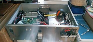
the transformer measured at 10 inches across when i removed the top. it has 3 transformer hold downs 2 are coated with a black insulating material and the third one over top the other two is a stainless steel wider hold down measures about 10&5/8 inches across that wider hold down.

the chassis box is the same form factor as the 26000 watt AMG but one thing i noted was the two round plugs to connect Thors Note Book are on the other end of the front panel... have to see if the transformer is on the other end but other wise it is the same size stainless steel case as the 26000 watt one...with the six round support feet on the bottom...

it is a heavy beast to maneuver around....wish I had it on wheels or a hydraulic cart but of course, I did not....Will Prowse showed a scissor jack hydraulic cart for loading his heavy server batteries onto a Dewalt rack...I need one of that type of scissor lifting cart or a Hoosier that they use to lift handicapped people into and out of bed....my back keeps telling me to get better tools....hahaha???

it appeared to have 24 mosfets on each short main board and 3 can-type electrolytic capacitors plus the red blob type capacitor on the short main boards... I could not see under the second control bard to get a good look at the second short main board but expect it is similar design...

so that would be 48 mosfets and six of the can-type electrolytic capacitors.....

did not see any shipping damage whatso ever ..... so that is a good thing so far....

I will have to tip it to get a picture of the lasered ASL transformer ring rating on the bottom of the stainless steel case another day...always forget something to do...

no charging or ups or LCD screens on this one,,,but I do have a Thor's Note Book I could hook up to it...with two LCD screens....

I do not want the charging as I will never hook it up to the grid.....strictly off-grid.....

it is a 2021 year model 20000 watt LF PSW SP PowerJack inverter...

yea yea buy the $1388 Victron multiplus that does 3000 watts if you want... you will need 3 of them (the victron multiplus 3000 for $4164 plus tax)
to do what the $427 dollar PowerJack including tax and delivery will do....

as I understand it the transformer in this Low Frequency(LF) Powerjack is isolated so does not have the neutral ground bond problem the imported HF inverters do...
It has L1, L2, and N plus the separate chassis bonding point.

1653826346448.png
 
Last edited:
the Sigineer 12000 watt LF inverter with built-in MPPT would be a good upgrade $3399, or the Sigineer 15000 watt $3299 or Sigineer 18000 watt Lf inverters are also good whole house options for off-grid use...
 
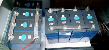
I also have smaller 15000-watt 3-piece PowerJack 24-volt LF PSW SP inverter that has been running continuously since August 2021 or so. It is hooked up to a 1088Ah 4P8S Lishen LiFePO4 battery(3.2x272Ahx4x8=27,852.8Wh or 27.83KWh) .... i think that 15000-watt LF PSW SP PowerJack was about $700 dollars delivered or so in the year 2021....

I suppose an 8k Solark inverter for $7,500 would be a good but very expensive upgrade vs a $700 dollar PowerJack.
I have another 40KWh of pre-fab LifePO4 (that cost $5600 dollars in the year 2019/2020) to hook up yet....for my off-grid project....

I think the Sigineer 18000 watt LF inverter would be the better investment though....??? I think it is about $3799 dollars currently....
for the off-grid whole house inverter at the off-grid farm.....
 
Last edited:
I also have smaller 15000-watt 3-piece PowerJack 24-volt LF PSW SP inverter that has been running continuously since August 2021 or so. It is hooked up to a 1088Ah 4P8S Lishen LiFePO4 battery(3.2x272Ahx4x8=27,852.8Wh or 27.83KWh) .... i think that 15000-watt LF PSW SP PowerJack was about $700 dollars delivered or so in the year 2021....

I suppose an 8k Solark inverter for $7,500 would be a good but very expensive upgrade vs a $700 dollar PowerJack.
I have another 40KWh of pre-fab LifePO4 (that cost $5600 dollars in the year 2019/2020) to hook up yet....for my off-grid project....

I think the Sigineer 18000 watt LF inverter would be the better investment though....??? I think it is about $3950 dollars currently....
for the off-grid whole house inverter at the off-grid farm.....
I have read and seen so many videos and thread responses on the POWERJACK elcheapos... what are the main detractions from them? Obviously they are listed at their peak output instead of the sustained output. They have no ul listings, they fail when loaded heavy for long times, and they Humm.
What in your opinion is wrong with them for a cheap split phase or 120V option? Are they dangerous? Do they have odd voltage wiring? I've heard they achieve 120V by sending split phase 60V not a true 120V single phase.? Similarly, their 240V cannot be tied into a regular panel?
 
PowerJack 15000 watt LF PSW SP inverter:

I am not an electrician:::::: so do your homework and study up or get professional assistance in all electrical work....Be Safe...

Do not work with live electricity....put in the shut-off or breakers 1st (be Safe)

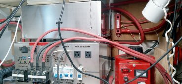
I wired the L1 and L2 to a 100 amp SquareD QO panel and the N neutral to the panel and installed normal breakers to outlets with no problem whatsoever. I used a 6 or a 4 AWG wire ( I will go check in a little bit) (all I had was red and black wire >>> so I color coded the black to white for the AC side wiring from the inverter (for the neutral wire) and used a green for the chassis ground to a ground rod....
All metal boxes are chassis ground connected to the ground rod.

standard red, black & white >>> with the red as the 2 hot wires L1 & L2 and the white ((relabeled with white tape at the Square D QO 100 amp panel)) as the neutral connection to the breaker panel.....

I do not connect to the grid....period.....I use it strictly off-grid

make sure you use a green wire for ground.


mine are all running 24/7 at a low load...
I get 120 volts out of each leg, it is a 15000-watt one wired to the breaker panel....
there is absolutely no grid connection in my system, nor will there ever be..

not UL listed...
they do not require UL listing to operate off-grid here....but that would be a plus if they were.
your situation may require a UL listed inverter....talk to your local electric inspector....

the PowerJack (aluminum wound enamel coated wire) toroidal heavy iron core transformer steps up the voltage to 230-240 volts and the center tap gives you the 120 volts....
I have had no problems....all electrical connections should be done with extreme care or find someone electrically inclined....

the only issue I had was installing the class T fuse after I had previously fired up the inverter>>> the capacitors still had a charge in the inverter(normal) but I did not anticipate the spark >>> so when I was connecting it to the 1088Ah battery that gave me a scare(excitement)???so I installed a shut-off switch on the large LiFePO4 battery and turned the inverter on while the battery was disconnected to run down the capacitors...I then hooked everything up without a spark.... the spark on a 1088Ah battery is enough to get your attention.... I recommend you wear safety glasses and gloves to insulate your hands for safety....be very careful with electricity....

this inverter brand (PowerJack) has been given a bad rap due to not outputting what they advertised, but the number they advertise is more likely the surge rating....just figure you will get half of the advertised wattage or less and you will not be as disappointed...

the newer AMG versions have 2 external N supposedly to foolproof those who do not understand electrical wiring...but my understanding is the 2 N's are the same N but added on the outside as people do not wire them correctly..... remove the top and you can see how they are wired....
you can wire them for 120 only, or 240 only, or split phase 120/240.... i wire mine as split phase >>> 120/240....

Disclaimer: I am not an electrician, but a DIY person, and if you have any questions about your electrical wiring ability....... please consult an electrician... use a multimeter etc,,,,

Have a great day all! ?

edit: keeping large PowerJack LF inverters cool with fans or a climate-controlled room will help some....most electronics work well at 25 degrees C which equals 77 degree Fahrenheit.... LiFePO4 also do better at this temperature....
Copper wound transformers such as in a LF Sigineer will need less cooling on their transformers at least that is the way they are designed...
 

Attachments

  • 20220401_081701_HDR.jpg
    20220401_081701_HDR.jpg
    598 KB · Views: 19
  • 20220401_081853_HDR.jpg
    20220401_081853_HDR.jpg
    447.1 KB · Views: 18
  • 20220401_081743_HDR.jpg
    20220401_081743_HDR.jpg
    86.8 KB · Views: 18
Last edited:
I have a PowerJack 20000 watt LF PSW SP 48-volt inverter and all the heat sinks have fins so you must be referring to a small batch design that did not have fins on the aluminum heat sinks... I heard on a video where they did that at one time....
the PowerJack inverter board converts dc to ac and then a toroid transformer with a center tap for 120/240 output jumps it up from the 34 volts to 240 volts... the center tap gives the 120-volt output...the PowerJack inverter will do 25 percent of its rated capacity in their line up.... what they are really advertising is the surge voltage when they talk of say a 20,000 watt powerjack 48-volt inverter..... the older ones would do 10000 watts....continuosly
can't say what the newer ones will do. in the LF inverter line...
but I just bought another one for $427.75 dollars on eBay auction that weighs about 94.6 pounds and has 48 mosfets 20000watt lf inverter. included free shipping (plus ebay tax) for $427.75 buy 2 get a spare for more power.

PowerJack 20000 watt LF PSW SP AMG received Friday May 20th, 2022:

the transformer measured at 10 inches across when i removed the top. it has 3 transformer hold downs 2 are coated with a black insulating material and the third one over top the other two is a stainless steel wider hold down measures about 10&5/8 inches across that wider hold down.

the chassis box is the same form factor as the 26000 watt AMG but one thing i noted was the two round plugs to connect Thors Note Book are on the other end of the front panel... have to see if the transformer is on the other end but other wise it is the same size stainless steel case as the 26000 watt one...with the six round support feet on the bottom...

it is a heavy beast to maneuver around....wish I had it on wheels or a hydraulic cart but of course, I did not....Will Prowse showed a scissor jack hydraulic cart for loading his heavy server batteries onto a Dewalt rack...I need one of that type of scissor lifting cart or a Hoosier that they use to lift handicapped people into and out of bed....my back keeps telling me to get better tools....hahaha???

it appeared to have 24 mosfets on each short main board and 3 can-type electrolytic capacitors plus the red blob type capacitor on the short main boards... I could not see under the second control bard to get a good look at the second short main board but expect it is similar design...

so that would be 48 mosfets and six of the can-type electrolytic capacitors.....

did not see any shipping damage whatso ever ..... so that is a good thing so far....

I will have to tip it to get a picture of the lasered ASL transformer ring rating on the bottom of the stainless steel case another day...always forget something to do...

no charging or ups or LCD screens on this one,,,but I do have a Thor's Note Book I could hook up to it...with two LCD screens....

I do not want the charging as I will never hook it up to the grid.....strictly off-grid.....

it is a 2021 year model 20000 watt LF PSW SP PowerJack inverter...

yea yea buy the $1388 Victron multiplus that does 3000 watts if you want... you will need 3 of them (the victron multiplus 3000 for $4164 plus tax)
to do what the $427 dollar PowerJack including tax and delivery will do....

as I understand it the transformer in this Low Frequency(LF) Powerjack is isolated so does not have the neutral ground bond problem the imported HF inverters do...
It has L1, L2, and N plus the separate chassis bonding point.

View attachment 96258
I have a PowerJack 20000 watt LF PSW SP 48-volt inverter and all the heat sinks have fins so you must be referring to a small batch design that did not have fins on the aluminum heat sinks... I heard on a video where they did that at one time. I have the 8000 watts PJ inverter that do not have fins on heat sink but it has 40 FETs and is using it for 3 years no problem . I brought at auction a 15kw PJ but they put in the 20kw transformer and is using it 24/7 on many sunny days for 3 years . The reason I will post here is the forum did not like me saying how good the PJ inverter are and really do not like the EG4 or Sungold . I hope Jack do not delay getting parts for the GS 12kw and fake shippings .
 
I have a PowerJack 20000 watt LF PSW SP 48-volt inverter and all the heat sinks have fins so you must be referring to a small batch design that did not have fins on the aluminum heat sinks... I heard on a video where they did that at one time. I have the 8000 watts PJ inverter that do not have fins on heat sink but it has 40 FETs and is using it for 3 years no problem . I brought at auction a 15kw PJ but they put in the 20kw transformer and is using it 24/7 on many sunny days for 3 years . The reason I will post here is the forum did not like me saying how good the PJ inverter are and really do not like the EG4 or Sungold . I hope Jack do not delay getting parts for the GS 12kw and fake shippings .
I am waiting to see the final gs12 and wonder if it is just a 26k power jack toroid core as they were surprised to see it as big or bigger than jack's gs12 special design!!! ? all of the extra features claimed non-functional warranty breaking features (of the non-UL gs12) on the gs12 have been out in other inverter brands for many years >>> so reinvent the wheel??? Sigineer can stack 6 and Sungold can stack 9 and eg4 can stack multiple as well and most have a wifi app etc...

LF may be better but I can not say for sure as I only have tiny HF inverters and never try larger HF inverters....
I am not an electrical engineer or electrician >>>> just a DIYer learning as I go with Solar PV off grid....
Have a great day all ?
 
Good to talk to you again . Bad news from Jack is parts to finish the production prototype is not available so shipping is delay for the GS 12kw . Sound like what ray jungle power do to you but hope the shipping is real . No parallel 240vac mode since Sid is still working on update and Sean is working full time to pay the utility . Running a load test on grid ATS is expensive .
 
Good to talk to you again . Bad news from Jack is parts to finish the production prototype is not available so shipping is delay for the GS 12kw . Sound like what ray jungle power do to you but hope the shipping is real . No parallel 240vac mode since Sid is still working on update and Sean is working full time to pay the utility . Running a load test on grid ATS is expensive .
very hard to get real results on a proto-type if they can not get the parts....I want to see the final version gs12 but it was not adequate for Sean's whole house and so far is not stackable so requires a set up of multiple breaker box independent systems for his 5000sf inefficient home.....maybe 6k is what their 12k reinvention will comfortable do at high efficiency....it is very interesting to learn of the LF pluses and minuses, but they try to guard the off the shelf component reinvention...I can not imagine paying for a pre-order that is not even at the final stage and waiting another 4 months or so while they continue to tinker with hardware/firmware that is already available on other brand inverters....their forum is primarily for hyping their product and not much support for powerjack inverters,,,just bash them (their own powerjack manufacturer)...waiting for powerjack-jack to send them some stuff....customers beware for sure....I am currently liking Sigineer and eg4 6500exfor stackability at the moment....the high voltage angle of Mike G was interesting but a battery build/buy is the stumbling part there...
have a great Thursday...?
 
the high voltage angle of Mike G was interesting but a battery build/buy is the stumbling part there...
The Sandi 30kw is the one to get with prebuit LiFEPO4 and is probably safe . I get a price of 4200 dollars for the 96vDC 12kw Sandi inverter and it is the same as 120vdc with MPPT solar controller and shipping included . I will need a inverter next year as the temperature is going down now. I can build a 96vdc battery safely . Sean on youtube say Jack can make the GS 12k in one week and ship to Sean by Aug 1 but now Jack told Genetry he can not get the parts so sound kind of fishy .
 
Back
Top