diy solar

diy solar

Could this work?

juanmijm

New Member
Joined
Nov 2, 2020
Messages
74
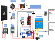
I am preparing the electrical installation for my camper van, I have created my first installation diagram, I would appreciate your opinions about it.

1605512900297.png

The fact of putting a dcdc and mptt to charge from the alternator is because I already have those devices, so if that works it could save me 160 / 280e which is worth a booster.
the balancer is an option, I don't know if I could leave it there always plugged in, probably not necessary, probably leave only the plug, to be able to put it manually in case it is necessary.
I also don't know if the shunt is in a good position, and if I have to connect the chassis GND with the ground of the AC sockets
And the last doubt is that I could put the alternator charge circuit to be able to operate remotely from the dashboard
Thanks for yours replies.
 

Attachments

  • 1BMSPNG.png
    1BMSPNG.png
    205.5 KB · Views: 11
Last edited:
No, the shunt is not in the correct position. It needs to be the gatekeeper between the BMS and the big bus bar.

Corrected the above.

Can you explain the presence of the EPEVER 40A unit? Is is connected to a solar panel or not? I don't see the need for it.
 
hi, thanks for replying, i guess you mean this position for the shunt.

Screenshot_20201116-184844_Outlook.jpg

the epever is to charge from the current that it would receive from a 12 to 28v dcdc which in turn is connected to the alternator, since the epever has a charging program and I can configure the parameters so that it charges without cutting off the bms.

the correct thing is to use a specific dcdc charger for that, but the mppt epever I already have it and would not have to spend the money on that...
still I think I am going to get it right and buy a dcdc charger.
 
Yes, the arrow is the right position.

I would put in a more "correct" DC-DC charger, mainly to reduce the complexity of the system. There have been some questions about plugging in sources to a solar charge controller that isn't a solar panel. I didn't follow those discussions closely and didn't see a final answer on if it worked well or not.
 
Last edited:
I have researched and asked a lot about this topic, but I have not seen anything clear working either, apparently the mptt has to receive at least + 2v than the output, so it could not charge directly from the alternator. that's why I had thought to put the dcdc in between.

thanks for the clarification of the shunt, then i will correct the schematic.
 
I see a circuit breaker between your solar panel and the solar charge controller. That's good. Many of us are also placing a circuit breaker between the solar charge controller and the common bus bar. The two circuit breakers would have different amp ratings since the solar panel produces a smaller amperage and the solar charge controller produces a larger amperage.

Before you buy circuit breakers, post a link to them. I bought the wrong circuit breakers twice. One circuit breaker was too low amp rating and could have produced nuisance breaks. The other circuit breaker was an AC circuit breaker when I thought it was DC. The first mistake was caught prior to the install, the second wasn't caught until after the install.

EDIT: I noticed that your second image doesn't have the circuit breaker, but still has the fuse. I bought in-line fuses for my install but didn't use them. Instead, I use the circuit breaker inside the trailer. This is sort of a convenience for me. If I need to work on the system I can shut off the power from the solar panel from inside the trailer without getting on the roof. Having both the fuse and the circuit breaker isn't wrong. Having just the fuse or just the circuit breaker is OK, as long as they are sized appropriately.
 
I used those small active balancers before and they didn't do anything for my battery. Since you will be charging from the alternator I recommend the qnbbm balancers, they are more expensive in the 100 dollar range for a 4s but they work very good, I had mine on my 220ah 4s battery (which use to always go out of balance at the top end) for the past 2 years.
If your charging at low amps, balancers aren't needed. The bms built-in balancing can handle it.


active balancers.jpg
 
I see a circuit breaker between your solar panel and the solar charge controller. That's good. Many of us are also placing a circuit breaker between the solar charge controller and the common bus bar. The two circuit breakers would have different amp ratings since the solar panel produces a smaller amperage and the solar charge controller produces a larger amperage.

Before you buy circuit breakers, post a link to them. I bought the wrong circuit breakers twice. One circuit breaker was too low amp rating and could have produced nuisance breaks. The other circuit breaker was an AC circuit breaker when I thought it was DC. The first mistake was caught prior to the install, the second wasn't caught until after the install.

EDIT: I noticed that your second image doesn't have the circuit breaker, but still has the fuse. I bought in-line fuses for my install but didn't use them. Instead, I use the circuit breaker inside the trailer. This is sort of a convenience for me. If I need to work on the system I can shut off the power from the solar panel from inside the trailer without getting on the roof. Having both the fuse and the circuit breaker isn't wrong. Having just the fuse or just the circuit breaker is OK, as long as they are sized appropriately.
How many amps should I put in?

I had thought about this one, which has a lot of sales with very good variances.
€ 6.24 | 2P DC 1000V Mini Solar Circuit Breaker, 3A 6A 10A 16A 20A 32A 40A 50A 63A DC Switch with MCB for PV System
 
On the input side of the solar charge controller, the amp rating of the circuit breaker depends on the max amps produced by your solar panel. Size the circuit breaker slightly higher.

On the output side of the solar charge controller, the 32a circuit breaker should be close enough, but the 40a would be OK too. With only a single solar panel, I don't think your solar charge controller will ever hit its maximum amp output. Given this, I would stick with the 32a breaker. As inexpensive as those are and given the long shipping time, I would be inclined to purchase both and maybe extras in case you expand the system or you break something.
 
I used those small active balancers before and they didn't do anything for my battery. Since you will be charging from the alternator I recommend the qnbbm balancers, they are more expensive in the 100 dollar range for a 4s but they work very good, I had mine on my 220ah 4s battery (which use to always go out of balance at the top end) for the past 2 years.
If your charging at low amps, balancers aren't needed. The bms built-in balancing can handle it.

I bought this balancer after watching this video, I will do the test as it only cost me 10eur, I hope it is not really necessary to use a balancer, and that my cells do not become too unbalanced.
 
On the input side of the solar charge controller, the amp rating of the circuit breaker depends on the max amps produced by your solar panel. Size the circuit breaker slightly higher.

On the output side of the solar charge controller, the 32a circuit breaker should be close enough, but the 40a would be OK too. With only a single solar panel, I don't think your solar charge controller will ever hit its maximum amp output. Given this, I would stick with the 32a breaker. As inexpensive as those are and given the long shipping time, I would be inclined to purchase both and maybe extras in case you expand the system or you break something.
1605559905888.png
this is mi solar panel,
Is the circuit breaker that I should put according to those amps? 10a seem few, 16 many?
for the other side I will take the 32, because since it is not inclined, I do not think that the 100% plate will ever be.
Should I put another one between the dcdc charguer and the bms?
 
10a seems to be cutting it a bit close. I would go with 16a.

I don't have a circuit breaker between my AC-DC converter and my common bus bar. Some installs do.
 
10a seems to be cutting it a bit close. I would go with 16a.

I don't have a circuit breaker between my AC-DC converter and my common bus bar. Some installs do.
ok, I'll put the 16a, can I really put a circuit breaker in exchange for a relay? I like the idea of having a relay and a switch at the same time
 
The switch and relay you're talking about go between the alternator and your DC-DC charger, correct? That's a good solution, but I didn't think we were discussing that.

Here's what I thought we were talking about.

solar panel -> 16a breaker -> solar charge controller -> 32a breaker -> common bus bar
Yes, we were discussing that, but it was clear to me and I asked you the other question :)
 
I have researched and asked a lot about this topic, but I have not seen anything clear working either, apparently the mptt has to receive at least + 2v than the output, so it could not charge directly from the alternator. that's why I had thought to put the dcdc in between.

thanks for the clarification of the shunt, then i will correct the schematic.
I would use a a 12V DC-DC charge controller. A number of companies make them. My preference is Victron, so I would replace the two boxes you have connected to the alterator with an Orion-TR 12/12-30 Smart Charger. Like this one.


It is smart enough to only draw current when the engine is running (it measures your electrical starter battery voltage). It has an ignition switch input also. Plus it is compatible with "Smart" Alternators if your vehicle has one of those. You can configure the charge profile to your hearts content with this unit. I am using basically the same converter with a 24V output for my Ford E350 system, an Orion-TR 12/24-15 Smart Charger.
 
I see you already switched to using a DC-DC charger that is fine. It is really hard to read the text in your image. What are those little orange boxes in the charge input wires? Are they fuses?
 
Back
Top