diy solar

diy solar

12v 560AH Build For Overland Van

I got a weak cell fault when testing, so I checked the BMS internal resistance measurements for the first time. They were pretty varied, with one cell over 1mohm, and others near 0.5mohm. I should be seeing around 0.2 max, and really 0.12 nominal. Though it will vary with SOC and temperature.

I bit the bullet and opened the cover. Nothing seemed out of place. So I took all the busbars off, and polished them with 1,000 grit paper. Easiest method was to oil my belt sander with a 1000 grit belt. I should have paid closer attention, but the 200 grit I used before was not up to the task, and I saw the scratches when I got a few passes in.

Reassembled and torqued to 35 in-lb. Results show below at nearly full charge. Much better. The values do fluctuate a bit, but should be fine for my application.

1599853969958.png
 
Did a full discharge test. Called it done at 520AH. Looks like all 560AH are available, but I going a bit conservative. I will post up a graph when I have a chance.

Tested the alternator charging and control. For the naysayers about "alternator meltdowns", I had my 200A alternator pegged at ~100-120A for an hour in 85F temps low idle only. The main case never got over 150, and the outer windings maxed out around 180F. This was measured with my IR thermometer, which is plus/minus 10F accuracy at those temps. With the pack at around 20% SOC actual, the alternator was outputting 13.46V, and the pack was at 13.17V. With no charging source the pack was at about 12.9-13.1V before settling. My pack is around 0.5-1mohm at this SOC/temp.
 
Here is the voltage, I tried to smooth out some of the noise, but this about as good as its going to get. Discharge was at about 140A. Charge was at 110A.

1599953466267.png


Here is the tail end of the charge cycle. The discontinuity in the middle is when my laptop went to sleep for a bit.

1599953436791.png
 
Really nice build! I have the same intended use, but you are moving much more quickly than I am. I have limited fab skills so would not try hanging the battery under the vehicle. I made packs of 4 using 1/4 aluminum at the ends - online metals has 8x8 plates which fit the wide side of these cells without cutting.and also leave room for 1/4” threaded rods on the long outer edges. 1/4 end plates also drop right into 1010 T slot, which is convenient.

I crank the packs down pretty solidly. The EVE data sheet suggests compression (around 12psi) extends cycle life and that is about 700lbs across the cell. I think that is about preventing the swell/shrink from SOC degrading the electrodes. They last a long time without it also, so I wouldn’t bother other than to need to have a solid pack I can pick up.

Nice use of braid as well - how many layers? I didn’t use MMC braid but have some and it’s rated for 85A so multi layers are required.

A quick observation - I saw you had a cable passing through the box. If you haven’t already done so a grommet or something to keep the cable away from the raw edge would be good.

All the cables have 1/16" rubber grommets, or a cable gland/nut depending on size.

On the braid Its actually 2/0 flat ground strap. So just one contiguous woven strap. I am getting around 1mA drop at 150A (per bus bar), so the resistance is pretty low.

Interior mounting is superior in most cases. Much easier environment and packaging. In my case, we full time in the van, and every cubic foot of storage is precious.
 
Back on the road full time. The pack is doing fine. I need to get the BMS SOC and pack health settings calibrated at some point.

I don't typically see the pack more than a few degrees above ambient. I did a C/4 charge and discharge cycle during testing, and it got to about 10F max above ambient.

Alternator charging has been working fine when I need it. Solar has been keeping up for the time being, but that will change as the days shorten. I have noticed that the alternator voltage can spike to 15.2V if I disconnect the pack during a peak current charge (about 150A when cruising down the highway). No harm to the van itself, as all the modules are good to 16V minimum typically.
 
Still working great and full timing with the pack. I am typically cycling the pack 30% every day sometimes more. With 50% of my amp hours coming from alternator charging. Cells are still well balanced.

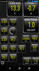
Heater Seems to be working just fine, and the pack stays between 39 and 45° when it's cold. It is very windy today and the low was in the teens.

Screenshot_20201126-112124.png
 
Back on the road full time. The pack is doing fine. I need to get the BMS SOC and pack health settings calibrated at some point.

I don't typically see the pack more than a few degrees above ambient. I did a C/4 charge and discharge cycle during testing, and it got to about 10F max above ambient.

Alternator charging has been working fine when I need it. Solar has been keeping up for the time being, but that will change as the days shorten. I have noticed that the alternator voltage can spike to 15.2V if I disconnect the pack during a peak current charge (about 150A when cruising down the highway). No harm to the van itself, as all the modules are good to 16V minimum typically.
These seem to be popular to protect an alternator from a sudden load disconnect.


Pretty cheap insurance at about $65.

I am curious how you converted the ML RBS latching pulse signals for "on" "off" from the constant high/low signal from the Orion. Could you possibly explain that in a bit more detail?

MP
 
I am curious how you converted the ML RBS latching pulse signals for "on" "off" from the constant high/low signal from the Orion. Could you possibly explain that in a bit more detail?
There is one version of the ML RBS which uses constant signals instead of pulsed signals. It has internal logic to handle this.
 
I saw a post on a YouTube video that said the 280ah cells plates are too thin for mobile usage and are likely to crack... Any truth to that? It said 100ah to 200ah is the preferred cells due to plate thickness... I have 250ah AGMs now and have been researching, when I found that I was discouraged... The 280ah seem like a great option if they can be used in a mobile application.
 
There is one version of the ML RBS which uses constant signals instead of pulsed signals. It has internal logic to handle this.
Thxs for your reply. I'm aware that the ML version 7713 can function this way. Is that the ML version you are using?

I just happen to have a ML 7700 ( which needs the pulse signal) sitting in a drawer collecting dust and wanted to use it for a new build I am undertaking. Searching for an elegant relay logic control solution for the latching relay 'pulse' signal from a BMS high/low signal. This for the Electrodacus BMS, so max 50 milliamps switching. Similar to the Orion.
 
I saw a post on a YouTube video that said the 280ah cells plates are too thin for mobile usage and are likely to crack... Any truth to that? It said 100ah to 200ah is the preferred cells due to plate thickness... I have 250ah AGMs now and have been researching, when I found that I was discouraged... The 280ah seem like a great option if they can be used in a mobile application.
Sounds like total bullshit. These cells almost all about use the same laminate thickness. There are no "plates". Did this person tear down cells and measure? Or do they just repeat crap they read online for views?

With proper clamping and protection there is nothing to worry about in my opinion.
 
Thxs for your reply. I'm aware that the ML version 7713 can function this way. Is that the ML version you are using?

I just happen to have a ML 7700 ( which needs the pulse signal) sitting in a drawer collecting dust and wanted to use it for a new build I am undertaking. Searching for an elegant relay logic control solution for the latching relay 'pulse' signal from a BMS high/low signal. This for the Electrodacus BMS, so max 50 milliamps switching. Similar to the Orion.
I am sure you could design a circuit to do that conversion. the difficulty is with ensuring that it is failsafe. So in the event of a BMS failure the signal will reliably return to off. There are numerous analog circuit designs which are designed to detect a change in signal state. Such a circuit could very easily be rigged up to provide a pulse anytime signal changes states.
 
I started getting a voltage run on cell 4 when charging at 100+ amps. Doing a discharge test showed 50mv drop on that cell at ~200A. My guess is that I have a loose busbar or connection.

So the pack cover needs to come off sometime soon. I need to do some work on the rear storage area, which will happen at the same time.
 
Back
Top