diy solar

diy solar

Questions about my 12v system

rogerball0

New Member
Joined
Feb 18, 2021
Messages
21
Hi There

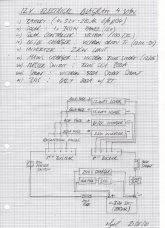
With prices of prismatic cells very reasonable i decided to make the change to Lithium by purchasing 4 x 3.2v 280Ah LifePO4 batteries and a 200A Daly BMS. This is to replace my existing AGM set up. In the process i want to rework my electrics cabinet in the van and drawn a simple wiring diagram of what i want with a components list of existing parts and parts i will purchase. I'm looking for someone to play devil's advocate with my wiring design as i'm an amateur at this electrics stuff (joiner by trade)

A couple of questions:

I want to know if I can i use resettable fuses off the positive fuse holder/busbar instead of ANL fuses after the master switch? I was initially looking at the Victron Modular mega fuse holder (5 position busbar) and then thought about a simple busbar bolted into an enclosure with resettable fuses coming off of each position.

The biggest load is my 2000W inverter and the solar panels I intend fitting on the roof (either 3 x 120W panel or 1 x 360W panel so 30A draw). Other than that there's no huge current draws as all my appliances are 12v: laptop, car radio, fridge, diesel heater & water heater.

Also is it good practice to connect the Solar Charge controller directly to the battery as i have done in my diagram?

Any feedback appreciated

Cheers

Roger (UK)

*EDIT* With the Victron mega fuse holder how is the busbar made live? Is it via a ring terminal around the large bolt or do i attach an ANL fused connection from the 300A master switch to the first fuse holder position? Thanks in advance. I've also changed the format of my doodle from PDF to JPG as i realised it tries to download, now it opens in the same window. Ta Tar.
 

Attachments

  • Diagram.jpg
    Diagram.jpg
    203.2 KB · Views: 25
Last edited:
A few comments:

the inverter: since you have a bunch of Victron equipment- I would put a Victron Multiplus 2000 inverter/charger in your system (unless you already have the inverter). This could eliminate the 240v charger

Fuses: with the Lithium batteries it is recommended to use a class T fuse - these can handle the super high amps that lithium’s can deliver. You only need one of these expensive fuses - just off the battery. You want all the positive stuff to flow through this fuse.

It doesn’t matter if you connect the solar charge controller to the battery directly or to the bus bar - BUT, yours is connected incorrectly. The negatives MUST go through the bms and Smartshunt. Otherwise, the bms cannot break the connection for those items if they are causing a problem to the battery, and because they are not going through the smart shunt the power they use and generate will not be the Smartshunt’s data (the Smartshunt will say the battery is at 51% - when it is actually full because it was not counting the power the Solar was delivering. (I would move all those to the buss bars - keep it as simple as possible).

One other option since you will have all Victron equipment- look at a Victron GX device (Cerbo or CCGX). (Watch some YouTube on it). It combines all the data from the Victron stuff into one place that makes it easy to see what’s going on at a glance. (It is expensive- but I think it is worth it - it will also control the Multiplus- so it saves a different controller.

I would think resettable fuses would be fine - but fuses should not go out often- if ever - so they may not be worth the additional cost.
Also add a resettable fuse on the positive wire from the solar panels to the solar charge controller- that way you can turn the sun off for testing and troubleshooting.

Good Luck!
 
Hi Rodger, In your diagram, connect the 240v charger and the solar charger to the positive and negative buss bars. I am not too sure what you mean by re settable fuses, ( if you are referring the Ebay type dc breakers, they are unreliable and poor quality). I recommend midi and mega fuses in suitable fuse holders,

link fuses

A distribution fuse holder can replace the positive buss bar,

distribution fuse block

At the positive battery connection , as near as practical, fit a class T fuse or as an alternative for a 12v system, a MRBF , (cube), fuse.

This fuse holder for the MRBF fuse,

fuse holder


distribution fuse.jpg
The battery negative connects to the BMS, the BMS output to the shunt, the shunt output to the negative buss bar. All other negatives from chargers and consumers connect to the negative buss bar.

Mike
 
Last edited:
Hi RM thanks for taking the time to reply to my questions.

A few comments:

the inverter: since you have a bunch of Victron equipment- I would put a Victron Multiplus 2000 inverter/charger in your system (unless you already have the inverter). This could eliminate the 240v charger
I've been interested in the Victron kit for sometime and like the fact you can network everything so have a bit more piece of mind. I was planning on keeping my 2000w/4000w peak pure sine inverter (chinese cheapy) but will see what the pennies are like near the time.

Fuses: with the Lithium batteries it is recommended to use a class T fuse - these can handle the super high amps that lithium’s can deliver. You only need one of these expensive fuses - just off the battery. You want all the positive stuff to flow through this fuse.
Understood, With regard to main fuse ratings am i right in assuming if the max continuous discharge current is 272A i rate the fuse to the nearest below that max rating? Apologies for dumb questions i cut and shape timber for a living.
It doesn’t matter if you connect the solar charge controller to the battery directly or to the bus bar - BUT, yours is connected incorrectly. The negatives MUST go through the bms and Smartshunt. Otherwise, the bms cannot break the connection for those items if they are causing a problem to the battery, and because they are not going through the smart shunt the power they use and generate will not be the Smartshunt’s data (the Smartshunt will say the battery is at 51% - when it is actually full because it was not counting the power the Solar was delivering. (I would move all those to the buss bars - keep it as simple as possible).
Yeah my diagram was super basic and incorrect, thanks for the help, thats what i want to avoid by updating my installation to Lithium is the birds nest i currently have on my AGM battery terminals hence the question about busbar/fuse holders, so i can i come off the battery negative with the BMS then shunt and move the MPPT to the busbar. Great.
One other option since you will have all Victron equipment- look at a Victron GX device (Cerbo or CCGX). (Watch some YouTube on it). It combines all the data from the Victron stuff into one place that makes it easy to see what’s going on at a glance. (It is expensive- but I think it is worth it - it will also control the Multiplus- so it saves a different controller.
Thats exactly what i want to achieve by going over to victron, i can have it all on the phone via BT & accessible, been watching a few vids on YT and the costs for the kit apart from the charger /inverter are all on a par with other brands.
I would think resettable fuses would be fine - but fuses should not go out often- if ever - so they may not be worth the additional cost.
Also add a resettable fuse on the positive wire from the solar panels to the solar charge controller- that way you can turn the sun off for testing and troubleshooting.

Good Luck!
I learnt this the other day from watching one of Will's vids. It suddenly dawned on me that the current still flows from the PV panels so makes sense to isolate. The resettables i was looking at were these:

fuse.JPG

Victron fuseholder/busbar i'm looking at:

2016-04-15_124742.jpg

And the batteries i've ordered:

battery.JPG

The other thing i'm a bit stuck on is the BMS, i'm struggling with the size required. I understand its size is based on the current that my 12v system uses but do i take the peak voltage from the inverter (4000W) into account or do i base it on its rating of 2000W. With my diagram above the potential current demand would be 400A. Is that a fair summation, any advice greatly received.

Cheers

Roger (UK)
 
Hi Rodger, In your diagram, connect the 240v charger and the solar charger to the positive and negative buss bars. I am not too sure what you mean by re settable fuses, ( if you are referring the Ebay type dc breakers, they are unreliable and poor quality). I recommend midi and mega fuses in suitable fuse holders,
Hi Mike, yeah those were the ones i was looking at, the thought was i could reset them rather than replacing with standard ANL fuses.
link fuses

A distribution fuse holder can replace the positive buss bar,

distribution fuse block

At the positive battery connection , as near as practical, fit a class T fuse or as an alternative for a 12v system, a MRBF , (cube), fuse.

This fuse holder for the MRBF fuse,

fuse holder
Cheers for the links to the above kit, i've had a few bits off them previously, any idea what the maximum rating is for that fuse holder?
View attachment 38218
The battery negative connects to the BMS, the BMS output to the shunt, the shunt output to the negative buss bar. All other negatives from chargers and consumers connect to the negative buss bar.

Mike
Thanks Mike, between you and Rocketman thats helped a lot.

Cheers
 
As far as bms size...

Yes your inverter can require massive amps if you run it at max. But the real question is what is the largest load you will put on the inverter? Continuous and surge.

you need to size the bms for everything you will run at once (plus a little extra- sometimes a lot extra).

since you have a 280ah 12v battery - a 200amp bms will probably be fine. But you want to still figure out your loads. a 120amp Overkill may work too - depends on your loads.

You also want to know the weakest link in your system. So you never exceed it.
With regard to BMS size can i do any damage to my batteries by fitting a BMS with a higher amperage rating than i need?
 
Only if you exceed the max discharge in amps of your batteries. Per the spec’s above - the continuous discharge is .5C and the max discharge is 1C. So with the 280ah batteries- your continuous discharge should be no more than 140amps and a max discharge of 280 amps.
 
I learnt this the other day from watching one of Will's vids. It suddenly dawned on me that the current still flows from the PV panels so makes sense to isolate. The resettables i was looking at were these:

View attachment 38792
Avoid those breakers like the plague! I have bought several of these types and they are not capable of handling the the current they claim. Also don't use AC breakers unless stated in specifications! Vast majority of AC breakers are designed to disconnect when voltage and current is near zero to avoid arcing. In DC circuits the voltage and current is not zero so AC breakers may fail to properly disconnect the circuit.

There are a few DC breakers I can suggest but I don't know where to source them in UK.
Eaton Bussmann 285 Series (Available up to 150A)
Eaton Bussmann 187P Series (up to 200A)
Eaton Bussmann 187F Series (up to 200A)
MidNite Solar MNEDC (up to 250A)

The MNEDC series is unpolarized. MidNite offers a variety of DC breakers. As you have a 30A Charge Controller then you should need anything larger than a MNEDC40.

Another resource for good breakers.
 
Last edited:
There are a few DC breakers I can suggest but I don't know where to source them in UK.

Regarding the battery load and the BMS, If the cells are 280Ah then in theory you can take 280 amps, 1C, continuously. It may be better for long life to limit to a lower value, say 200 amps. Using this value and ignoring inverter efficiency and load short term surges, that is around 2500 watts usable power.

Don't buy a 'noname' inverter of eBay. it wont meet specification and will fail within months.

You have the option of two types of BMS, units where the control of charge and discharge is with onboard semiconductor switches, or units that control relays, there is a section on the forum for BMS so have a look there.
Personally I prefer the semiconductor type as these can operate fast enough to handle faults. However there are often limits in the amount of current they can control. The well respected Overkill/JBD BMS has a 120 amp limit ( its reported that two units can be used in parallel).

Another option is to connect the inverter direct to the battery (with suitable fuse protection) and rely on the BMS to control all other loads and chargers. The remote enable on the inverter and/or its internal low volts disable would be the protection for the inverter.


Mike
 
Back
Top