diy solar

diy solar

Would this make good busbar?

pvdude

Solar Enthusiast
Joined
Feb 8, 2021
Messages
627
Location
Florida
After reading and reading again the Victron Wiring Unlimited document, I might connect the 8 Rolls 6v batteries using busbar, as they show in the document.
Went rummaging around in the scrap metal pile, found this 10mm thick piece of silver plated copper.
I can cut this up to make busbar.
What is the relationship of copper density to current?
For instance, if I make the bars 14mm wide, the plate is 10mm thick, is that enough mass for the current, so as to avoid unnecessary resistance losses?

I found this formula, looks like capacity of 168A , seems OK to me.

Take a copper bus bar of 100 mm width and 10 mm thickness, the area of the copper bus bar is 10 * 100 sqmm. The total current carrying capacity of the busbar is 1.2 * area => 1000 sqmm* 1.2 =1200 Amps.
busbar_option.png
 
After reading and reading again the Victron Wiring Unlimited document, I might connect the 8 Rolls 6v batteries using busbar, as they show in the document.
Went rummaging around in the scrap metal pile, found this 10mm thick piece of silver plated copper.
I can cut this up to make busbar.
What is the relationship of copper density to current?
For instance, if I make the bars 14mm wide, the plate is 10mm thick, is that enough mass for the current, so as to avoid unnecessary resistance losses?

I found this formula, looks like capacity of 168A , seems OK to me.

Take a copper bus bar of 100 mm width and 10 mm thickness, the area of the copper bus bar is 10 * 100 sqmm. The total current carrying capacity of the busbar is 1.2 * area => 1000 sqmm* 1.2 =1200 Amps.
View attachment 36957
That must have costed a fortune!
Do they have more?
 
What I've read is the day to day thermostresses as battery temperatures change can apply force on the lead connection points. Bussbars are OK, but they need to be flexible in some why so they don't amplify those stresses. Having them in a Ω shape would work well. That bar appears too heavy to add a bow?
 
Yes, there is some expantion and contraction.
Not just from thermal, but a full battery is actually more "round" then empty.
Sure, the outside corners won't move an inch, center of the thin aluminium goes little bit in and out.

That is why you read all about compress and why it's a good idea.
Snug fit is tight enough, you don't need to crush the cells.

Result of compression together is that the movement is reduced.
Thermally expantion/contraction of the cell is minimal.
Really Minimal.
Same for the bus-bar, as a good bus-bar fitted for the job doesn't get warm or hot.

We talk about 5 degrees difference.
Your compressed pack will be about 35-40 degrees under load.
With a room temperature of about 25 degrees.

In the few hours the sun isn't strong enough to provide your load and charge, your batteries are in rest.
And might get 1 or 2 degree less.

Set of 16*280 cells is 100 kg.
That is a lot of thermal mass.

Next step is how much more (or less you think the copper bus-bar will extend/contract compared to its attachment points, the terminals

And, you are sure that this is not build to be slightly flexible.
(Thin aluminium housing)

We talk about fractions of millimeters.
What perhaps could bring stress to the terminals.

"All" DYI LiFePO4 builders use bus-bar and bolt them down.
(I prefer headless bolts/rods, as it give more control over the incerting depth, and less stress on the threads when fastening)

I never have heard of anyone ever breaking terminals due to thermal movement of the bus-bar.

The bus-bar is the same temperature as the cell.
Aluminium and copper both conduct heat perfectly.

The bus-bar will act as type of heatsink for the cell.

Mind you, this is for solar installation.
Relatively slow charge, slow discharge.

In EV usage, cells get hot.
Tesla have them liquid cooled, for reasons.

For "us"... That's not a problem.

If you have an environment where the temperature difference is huge.
-10 in the winter (RV not used), +40 in the summer...
Yes, better flexible bars.

A setup like mine, "massive" 400kg block 60*60*70cm (has cooling gaps) I have 2 or 3 degrees difference in the center and the top of the cells.

Charging with +150A does give a temperature rise after hours of 1 to 3 degrees depending on current and time. (And SOC)

That's all.
5 degrees Celsius.

Sure, there will be some difference between aluminium and copper.
At 5 degrees on 10cm lengths.
With the fact that both copper and aluminium are flexible metals..

Sure.
One can invent problems where there are none.
And theoretically, yes there is a difference.
Train rails need 1 cm on 10 meter length to compensate for +20 and +80 (full sun)
Your bus-bar might need a tenth (or less) of a milimeter, if both metals would not be able to compensate.
And yes, in time the aluminium might rupture.
After 20.000 cycles you might be able to see fraction cracks.
After 100.000 it might even be real cracks.

For our usage in relative stable temperatures, don't need to worry about that.

Aviation.. again, different story.
 
Seriously? 10MM! Copper would be enough busbar for a massive load, silver plating it seems excessive.
Are you sure it isn't tin or nickel plate?
 
Yeah.. 10mm is a lot.

I have a 2 bars that are this thick, they combine 6 cells (2*3 parallel)
Totally Overkill, but I needed to have extra pressure in the center due weak threads in those cells.

Silver plated is relatively normal for electrical usage of copper as silver oxidation have almost no influence on its conductivity.

But yeah.. 10mm thick, 100mm wide, 100 cm long??

That should weigh about 8.5-9 kg.
 
I don’t know exactly how much current to expect, so having a difficult time calculating exactly how large to make the busbars from this chunk’o copper.
The manual for the Schneider 6848 says “180A DC, max DC current”
My batteries are going to be Rolls S6 L16-HC, 445Ah. (Picking them up in April)
So if I cut the bar into pieces w/ a dimension rated for about 200A, will that be sufficient?
 
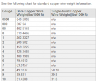
I think you could measure the weight of a specific length of this bar, and then use the table below to calculate what it can handle. Looking at the chart, you could start at 1 foot of 4/0 wire weighing 0.6405 lbs. Then go from there. Assuming that 4/0 wire can carry 195amps, then a 1 foot section of bar weighing >0.64 lbs could carry at least 195A.
1614646642553.png
 
I personally just figure out the area involved and compare to wire and use wire gauge charts to figure it out. If it's 2mm thick by 10mm wide then find the AWG equivalent of 20mm^2 (2 * 10) wire and run your calculations through that. The bus bar chart previously mentioned is good, too.
 
It's a lot of fiddling around with numbers, inches gauges, mm2, mm and cm!

Your bar is 10mm thick.
That's huge.

Your terminals will have M6 or M8 mount (or inches equivalent)
Logic makes that the bar is minimal 10, better 12 but probably 14mm wide.

@ 12mm ,you don't have to worry about anything below 500A
 
well, as others have points out, when it comes to current the cross sectional area is key.
I like my conductors to always stay "cool" so I look at the max current the system can produce and add at least 50% margin.
bus bars are usually right on the batteries, so those should be sized for the safe current capacity of the battery.
after that, keep in mind it is what the system can produce, not what it has...
So if you have a 200amp BMS, I would size conductors for 300amp. (50% bump)
if you have a 1000000amp/h battery with a 20amp fuse, well, the sizing after the fuse has a max of 20amps so 30amp capacity is enough hehe

do not forget to take into account your wire resistances as well, remember the wire resistances are: inverter TO the load, plus.. load back to inverter...always multiply inverter to load by 2 to get the actual wire distance your current must travel :)
wish I could find some copper like that just laying around!!
 
Back
Top