diy solar

diy solar

EVE 280Ah acceptable Internal Resistance?

AC IR is typically 10-25% lower than DC IR. At high frequency AC the pack has a small amount of capacitance. Capacitance reduces impedance, but has no effect on resistance (DC).

When we talk about AC/DC IR we are really referring to impedance and resistance.
 
Last edited:
AC IR is typically 10-25% lower than DC IR. At high frequency AC the pack has a small amount of capacitance. Capacitance reduces impedance, but has no effect on resistance (DC).

We we talk about AC/DC IR we are really referring to impedance and resistance.
Yes, AC measures impedance while DC measures resistance. But it’s the battery manufacturers that created the confusion by labeling their spec Internal Resistance instead of Internal Impedance.

Are you saying the Internal Resistance of ~0.4 mOhms I measured would likely translate to a measurement of ~0.3 to 0.36 mOhms using one of those AV IR testers?

Have you been able to measure lower dV/dI IR values than 0.4 mOhms and if so, what was the trick, higher currents?

Also, will the dV/dI technique work just as well with different charge currents as it will with different discharge currents?
 
Are you saying the Internal Resistance of ~0.4 mOhms I measured would likely translate to a measurement of ~0.3 to 0.36 mOhms using one of those AV IR testers?
If you can account for contact resistance, which is the issue of course.

Have you been able to measure lower dV/dI IR values than 0.4 mOhms and if so, what was the trick, higher currents?

The orion BMS on my vans pack shows about 0.2 mOhm for each 2P cell group. This is after I compensated for the bus bars, which was just a matter of running a known current through the pack and measuring the drop across each bus bar.
Also, will the dV/dI technique work just as well with different charge currents as it will with different discharge currents?
I believe so. However at 100% SOC the resistance will spike, so the max DI is limited. Obviously a mid SOC would be required in this case.
 
If you can account for contact resistance, which is the issue of course.
Meaning that the AC-based impedance measurement is less impacted by contact resistance, or am I not understanding correctly?
The orion BMS on my vans pack shows about 0.2 mOhm for each 2P cell group. This is after I compensated for the bus bars, which was just a matter of running a known current through the pack and measuring the drop across each bus bar.
So you can measure IR using the dV / dI technique at the battery level - hadn’t thought of that.

That gives you a measure of average internal resistance but I suppose with measurements at individual busbars, it can all be figured out.


I believe so. However at 100% SOC the resistance will spike, so the max DI is limited. Obviously a mid SOC would be required in this case.
I just measured in the cell I am charging at 10.2A and I measure 1mV difference from 1 end of the busbar to the other, meaning 0.098 +/- 0.49 mOhms per busbar (obviously would be better to measure at higher current with my DMM).

From busbar to stainless bolt I get another 1 mV and from the combo of far end of busbar to nut I get 2mV (meaning 0.147 to 0.245 mOhms through busbar and into bolt and I read 0mV from bolt to terminal and 2mV from the far side of the busbar to the terminal, meaning the same 0.147 to 0.245 from busbar and into aluminum.

So now if I subtract the busbar + bolt resistance from the 0.47 mOhms I measured using dV / dI directly on the terminals, I get

0.473 +/- 0.0473 mOhms
- 0.196 +/- 0.049 mOhms
= 0.277 +/- 0.0963 mOhms

So I’m getting pretty close to the specification and should be precise enough to measure IR of individual cells for purposes of relative comparison (though being able to drain or charge higher currents would be nice).
 
Meaning that the AC-based impedance measurement is less impacted by contact resistance, or am I not understanding correctly?
My understanding is that these meters are calibrated to adjust for contact resistance when using the typical probe/lead.


That gives you a measure of average internal resistance but I suppose with measurements at individual busbars, it can all be figured out.
The Orion (and other BMS) actually measure each cell. They have cell taps and know the current, the rest is just math. With the bus bar compensation entered its a great tool for high current applications especially. Tracking down that one loose nut is much easier this way. One of these days I will do a charge/discharge cycle on my vans pack, and plot the IR at various SOC. It takes a while, as I need to stop the charging/discharge for a few seconds to drop the current down, so the BMS can do the delta comparison.
 
I built a 2p16s pack (32 cells) about 4 months ago. Although the battery was working great, some cells (2p) where discharging faster than others. I decided to measure the internal resistance and combine the lowest resistance cells with the higher resistance them to balance the 2p packs to see if they will discharge evenly.

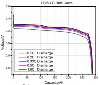
I think the resistance should be tested around 3.3 Voc where the curve is flatter. I also think the discharge current should be as high as possible, not greater than 1C (280A). I just started testing my pack and wanted to share my results, I am no battery expert so any recommendations are appreciated.
Screen Shot 2021-05-03 at 4.04.08 PM.png

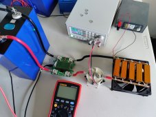
I built a tester using the DC load method and the results for the first three cells are between 0.34 and 0.36 mOhms. My tester consumes around 87A. I didn't had more resistors, I would have liked to test at least 140A (0.5C). The fan is not necessary, the load will only be active for a couple of seconds.

IMG_20210503_155149.jpg
 
Back
Top