diy solar

diy solar

2 identical batteries in parallel, but unequal discharge?

Steve Dally

New Member
Joined
May 10, 2021
Messages
16
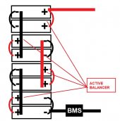
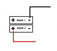
So, I'm not sure what's going on here... I built up 2 separate batteries, each one with brand new 3.2v 280 amp hour lifepo4 prismatic cells, 4s configuration, using an overkill BMS on each. Then the two batteries are in parallel to the positive and negative bus.

Everything seems great except this: they aren't discharging equally during low draw loads. A 5 amp load, for example is pulling 4.5 Amps from one battery and a half amp from the other. Larger draws (100 amps for example) pull equally from the batteries.

The weird thing is that this wasn't happening the the first 3 weeks after I installed them, it just started a few days ago, when I noticed that one battery was down to 80% and the other was still at 99%.

Am I right to be concerned by this? Any ideas of what might be causing it?

Here's a little background info, just in case it's helpful:
I top balanced all of my cells prior to building the batteries. Both batteries were charged to 100% (I'm calling 3.5v for cells and 14.0v for pack a 100% charge)
 
Hello
By 2 separate batteries, you mean Banks (4s 3.2v 280ah = 12v bank)
just to get you right, you have two 12v banks connected in parallel aim of getting 12v 560ah?
if so, then its likely your cell batch might not be same despite having same capacity, so might have different resistance.
or your configuration,
you can try this below, or the image attached:

Since you have 2banks in parallel, your positive output should come from 1 bank while your negative output from the second bank. (IMAGE ATTACHED)
otherwise you can get an active balancer with higher Amp from 5-10A or more (can as well parallel some active balancers for higher amp) and do the below image.
 

Attachments

  • Screenshot_4.jpg
    Screenshot_4.jpg
    65.9 KB · Views: 98
  • Screenshot_3.jpg
    Screenshot_3.jpg
    17.7 KB · Views: 90
Okay! First of all, thanks for the help on the nomenclature ('bank' instead of 'battery')! Second, i think I messed up on how to put them in 'parallel'... I simply connected both, separately, to a common fuse which then goes to positive bus, instead of connecting A to B and then B to the fuse. I fully understand, with the help of the image you provided, what you mean by connecting the positive of one and the negative of the other. Thank you, thank you, thank you! I can't wait to dig back on to my system and make it right! I'll post an update in a week or so!
Thanks again,
Steve
 
Very interested in this as I’m seeing something similar. What doesn’t add up for me in your diagram is the single BMS. Could this apply for a 2 BMS setup?

Ive connected positive battery one and positive battery two to a bus bar then to a main terminal, same setup for negative with the exception that the output from each BMS is connected to the bus bar. Under various conditions I’ll see via the BMS app, different discharge amperage.
It sounds like you and I have nearly identical setups. The comment that MCharles made about connecting the positive of one bank, but the negative of the other bank is going to be, i think, the key. The first pic below is my current setup. It seems parallel to me, but check out the second diagram... I'm beginning to understand (please correct me if I'm wrong) that this is properly parallel. 16274038798237405268971240177530.jpg16274039316311792638848810593411.jpg
 
It would appear to me that the second (by hand) drawing would create a situation where the failure of one BMS would kill the whole system. I prefer the upper hand drawing - and it is the busbar configuration that I use (with more batteries). I find it more flexible for maintenance and charge/load management.
It sounds like you and I have nearly identical setups. The comment that MCharles made about connecting the positive of one bank, but the negative of the other bank is going to be, i think, the key. The first pic below is my current setup. It seems parallel to me, but check out the second diagram... I'm beginning to understand (please correct me if I'm wrong) that this is properly parallel. View attachment 57869View attachment 57870

And as I understand it, bank refers to all assembled batteries - as combined into a single input/output to charger/inverter/loads.
Perhaps @Steve_S or @GXMnow would chime in...
 
Bank = any two or more complete battery packs working in concert connected to a Common Bus.
Pack = 1 completed battery assembly with BMS, Fuse - if used independently then commonly just referred to as "battery", I know, weird LOL.

I have two banks: Bank one, has 5 LFP Packs connected to a common DC bus. Bank two, has 8 Rolls Surette S-550's 4S2P connected to the Common DC Bus. Either Bank can be active or both combined (with care & caution due to the chemistry differences).
 
@Steve_S Any thoughts on that wiring setup or the uneven discharge? I also have two banks, but both are LFP - although, I have a AGM battery that can be switched in if/when I want to take all the LFP offline.
 
There can be MANY factors at play, from wire gauge & lengths to Lug Compression, battery cells & BMS (different AH cells in a bank) or even having misbehaving cells in any pack can toss things out of whack. All lithium chemistries are far more sensitive to such things,
 
It sounds like you and I have nearly identical setups. The comment that MCharles made about connecting the positive of one bank, but the negative of the other bank is going to be, i think, the key. The first pic below is my current setup. It seems parallel to me, but check out the second diagram... I'm beginning to understand (please correct me if I'm wrong) that this is properly parallel. View attachment 57869View attachment 57870

I don't see anything wrong with your first example of a battery layout. It should work and as you said it worked fine for several weeks. Sounds like possibly a bad connection or BMS setting in the battery that has the low voltage drop (99%). This would cause the battery with the high voltage drop (20%) to supply the load. If you have a Multi Meter with a DC amp clamp check the current in the 2 wires going to the bus bars for a difference. They should be near the same at all loads if the batteries are the same and also the wires are the same length.

One possibility is that the bad connection is overcome at higher loads and higher currents.

See the attached pdf in resources on this site that FilterGuy put together for battery layouts.
 

Attachments

  • LiFePO4 Cell Configurations.pdf
    506.9 KB · Views: 82
Last edited:
Regarding the bank vs battery comment. I know yall have already debated it but:

Multiple cells is called a battery.
Multiple batteries is called a bank.
Multiple banks is called an obsession. I would also call it "Will Prowse".

Either could be called a "pack".


Personally I don't really care either way, but it was mentioned.
 
This is very common and normal.

Any tiny difference in the internal cell voltages, state of charge, cell resistance, BMS resistance, and even the voltage drop of the mosfets will cause the two separate battery strings to carry a different amount of current.

But in the real world, it also should not be a problem, as long as you plan for it. When you start to pull current, one battery supplies more current. That will cause that battery to discharge a tiny bit faster, and at some point, that battery's internal voltage will drop to where the other battery will start to carry more of the load. After that point, the cells will self balance. With LFP cells, the voltage change is very slow, so it can take a while to get there.

What I have told people before is that when you parallel multiple batteries, you can't ever expect to get the full current. MY own personal rule is two batteries, 150% current of one battery. So with two batteries each capable of 100 amps, with 2 in parallel, you can pull 150 amps, so even if there is a 50 amp difference, the high battery is only at 100 amps, and the low one is providing the other 50 amps. Go to 4 batteries, and now you should be safe pushing 225%. This is again getting 50% more current when you double the batteries. If the balance is perfect, then you would only have 56.25 amps from each battery, but if one is weak, and another it strong, you could have one pulling 85 amps, and one pulling just 20 amps, while the other two are at 60 amps.

After the batteries cycle a few times, they should find a balance where they share the load fairly well. The weakest string will run a little less current, and the strongest string a little more, but the difference should fall over time. With LFP cells the current will probably be a little worse as the state of charge has to change quite a lot to get the internal voltage to move much at all. I am currently running two strings of Li NMC cells, and I do see the current between the pair differ by as much as 6 amps when running an 80 amp load. That is totally fine for my design as I am running well below the maximum current of even a single string of cells. Each of my strings are rated for a 3C constant discharge, which works out to 540 amps. I have them fused at just 125 amps due to my #2 awg wire and my BMS limitations.
 
I have also observed that with a 100A Load is called for the 280AH Packs will discharge more amps than the 175AH Packs in the bank, and similarly, during charging the 280AH packs take slightly more amps than the 175's but the 175's hit full state first and the charge balance then goes to the 280's (at the end) and then during float, they all level up nice & flush @ 100%, and all the cells in the packs then balance out typically at 10mv or lower differential.

In my installation and which I generally recommend to people, is to make Each Pack within a Battery Bank be able to handle the Max Charge & Discharge capabilities of the system, so they can operate as a "Last Man Standing" in the Bank if all the other packs cut off for any reason.
 
Okay, so it's been a week since I first posted... Thank you everyone for adding your wisdom and experience to help me out. What a truly great and supportive forum!
Here's what I did. I rewired things as was first suggested such that they are truly in parallel.. like the 2nd of my drawings in my earlier post (using the positive of one battery or pack, and the negative of the other). I also really cleaned up all of my terminals, lightly sanding, then brushing with a bronze brush, cleaning with alcohol, before reconnecting everything. After reassembly, everything seems to be nicely balanced. unscientific, on my part, changing two variables at a time, so I'll never know if it was the wire routing or the cleanliness of my contacts/connections, but I suspect the latter, seeing that my system was working so well in tandem at the beginning... it kind of makes sense that maybe a contact loosened or something. Anyway, all is good in battery land.
Thank you, again, everyone!
Steve
 
I don't see anything wrong with your first example of a battery layout. It should work and as you said it worked fine for several weeks. Sounds like possibly a bad connection or BMS setting in the battery that has the low voltage drop (99%). This would cause the battery with the high voltage drop (20%) to supply the load. If you have a Multi Meter with a DC amp clamp check the current in the 2 wires going to the bus bars for a difference. They should be near the same at all loads if the batteries are the same and also the wires are the same length.

One possibility is that the bad connection is overcome at higher loads and higher currents.

See the attached pdf in resources on this site that FilterGuy put together for battery layouts.
I think you were spot on with the bad connection idea! my shunts (i have one for each battery or bank) were telling me that the current was truly different during low loads, but near the same for higher loads. Thank you for the thoughts on this!
 
Regarding the bank vs battery comment. I know yall have already debated it but:

Multiple cells is called a battery.
Multiple batteries is called a bank.
Multiple banks is called an obsession. I would also call it "Will Prowse".

Either could be called a "pack".


Personally I don't really care either way, but it was mentioned.
Thank you! This makes sense to me! 8 cells total, arranged in 2 packs, each in 4s with its own BMS. So my battery bank consists of two 12V batteries... but I agree, not a big deal, just like all nomenclature it just helps in our quest to communicate clearly
 
Thank you! This makes sense to me! 8 cells total, arranged in 2 packs, each in 4s with its own BMS. So my battery bank consists of two 12V batteries... but I agree, not a big deal, just like all nomenclature it just helps in our quest to communicate clearly
Unfortunjately I "generally agree that nomenclature should not be a stumbling block", but it can be because people with different levels of experience get things confused and then the subsequent responses get muddled as well.

The worst part is the Lead Acid Batteries have common terms which many use BUT which are not used in an identically with Lithium Based cells, even simple things like SOC vs DOD. Some of it is very subtle and some not so much.

The biggest hurdle is for people who are Not "Battery Conversant" at all and totally NEW to all of this... The "Alphabet Soup and meanings/distinctions do become a big hurdle and often resulting in major stress, anxiety & some just get fed up and wander off.
 
I had a similar experience after setting up my trailer system. I used a millimeter and looked for voltage drop across connectors and components and found a volt drop across a breaker. 2 banks connected with 4 wires to buss bars.
 
Back
Top