diy solar

diy solar

Growatt 48v 3000 Open Neutral

@FilterGuy
Grid Through Inverter UTIL mode: UNTESTABLE. GFCI in garage where inverter plugged into popped immediately, regardless if Transfer switch was set to Gen/Inverter, OFF, or Line/Grid for the circuit being tested.

Thoughts?
One possibility: A neutral-ground bond downstream of the GFCI will trip it. I don't know what UTIL mode means, so sorry if this is not-applicable information.
 
One possibility: A neutral-ground bond downstream of the GFCI will trip it. I don't know what UTIL mode means, so sorry if this is not-applicable information.
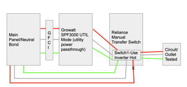
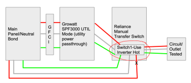
I tried creating this diagram about what I just tested, I know a bit confusing. The net is the inverter fed grid power to the circuit that was in the manual transfer switch set to use generator/inverter connection instead of grid connection. The manual transfer switch almost make it seem like the circuit is in a sub panel although it's in the main panel with the hots changed to use inverter.

The 15a breaker basically moves from main panel to transfer switch panel when in generator/inverter mode. When in LINE (Grid) mode in TS, the breaker I the panel is the active one.
Screen Shot 2021-10-30 at 10.12.44 PM.png
 
@FilterGuy
So that was an interesting test.
Baseline on Grid completely: No open ground from tester and can see 122v across Ground and Hot, same 122v with Neutral and Hot. Neutral and ground was 0.31v

Battery Only from Inverter: No open ground from tester and can see 118v across Ground and Hot, same 118v with Neutral and Hot. Neutral and ground was 0.23v

Grid Through Inverter UTIL mode: UNTESTABLE. GFCI in garage where inverter plugged into popped immediately, regardless if Transfer switch was set to Gen/Inverter, OFF, or Line/Grid for the circuit being tested.

Thoughts?
That is more evidence that there is a permanent Ground-neutral bond at the output of the inverter.

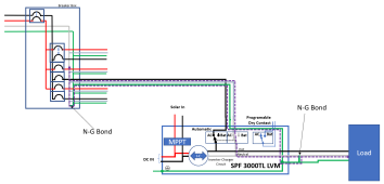
When the inverter switches to grid mode, it connects the line in to line out. Since there is a N-G bond in the house and an N-G bond someplace down stream of the inverter, the Neutral and ground are essentially wired in parallel. That means about half the current will try to travel across the ground wire..... and pop the GFCI.

If you plug it into a non-GFCI it will appear to work, but there will be current on the ground wire. In the diagram below, the purple dashed line is an attempt to show how the neutral current ends up on the ground wire.

1635646462326.png


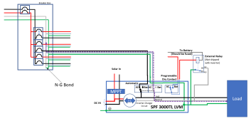
To prevent this there needs to be a dynamic N-G bond on the inverter output. The growatt provides a dry-contact output to facilitate the dynamic bonding.
1635646820544.png

The diagram above shows the circuit when the inverter is delivering power from the grid. Notice that there is only one path for the neutral current.
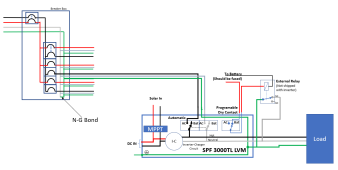
The following diagram is for when the inverter is delivering power from the battery.

1635647307853.png

If you want to learn more about the purpose of the N-G bond, please review this resource:
 
BTW: In my diagrams above, the inverter is drawn as a simplified conceptual model for the purpose of illustrating the grounding properties. In reality, it is much more complex than what is shown. As an example, The AC-in can be charging the battery at the same time as driving the output, but that would not work in the simplified model. (I need to work on that for my resource)

 
One more point: The timing of the dynamic bonding relay is important. If the AC is connected to the output before the bonding relay is opened, there will be a brief moment of two NG bonds. This would trip any GFCI. Sadly, some inverters get this wrong and can not be plugged into a GFCI protected circuit. I do not know what the Growatt does.
 
One more point: The timing of the dynamic bonding relay is important. If the AC is connected to the output before the bonding relay is opened, there will be a brief moment of two NG bonds. This would trip any GFCI. Sadly, some inverters get this wrong and can not be plugged into a GFCI protected circuit. I do not know what the Growatt does.
@FilterGuy
Glad I did this test to get a more real world understanding of this and thank you very much for your help. I know there is option 24 (discussed in other threads) with the relay. Assume the relay is the only real way to make these inverters save and use Neutral, unless you are never going to connect to Grid to AC-IN.

I assume UL Listed inverters such as Sol-Ark, Outback Skybox, SMA, AIMS have already figured this out and are doing the bonding properly as you never see this topic come up on threads with those products.
 
Ok @FilterGuy, this is starting to consume me. I hooked up our whole house vacuum to the Growatt 3000 to get some good 15a load on this, busted out my amp clamp meter and volt meter. Here are the results:

Growatt Test High Load:

Off Grid Battery Output Cable:
Amps:
  • G=0a
  • L1=14.98a
  • N=14.62a

Volts:
  • G/L1=55.64v
  • G/N=64.4v
  • L1/N=120v


On Grid UTIL Mode Output Cable:
Amps:
  • G=0a
  • L1=14.99a
  • N=14.61a

Volts:
  • G/L1=120v
  • G/N=2.3v
  • L1/N=119v
 
Growatt Test High Load:

Off Grid Battery Output Cable:
Amps:
  • G=0a
  • L1=14.98a
  • N=14.62a
This looks normal. (the difference in current is almost certainly a measurement error... the clamp on meters are just not that accurate)
Off Grid Battery Output Cable:
...

Volts:
  • G/L1=55.64v
  • G/N=64.4v
  • L1/N=120v
This is an indication the power circuit is floating and an N-G ground is needed. Does the 3 led circuit tester still show everything is OK?
On Grid UTIL Mode Output Cable:
Amps:
  • G=0a
  • L1=14.99a
  • N=14.61a
This looks normal

BTW: Did you plug the system into a non-GFCI to get this to work?

Also, can you measure the current on the input cable ground?

On Grid UTIL Mode Output Cable:

Volts:
  • G/L1=120v
  • G/N=2.3v
  • L1/N=119v
This looks normal. The circuit is 'seeing' the NG ground that is in your house breaker panel. The 2.3V is the voltage drop on the neutral line due to the load (there might be some measurement error too). If you turn off the load, the 2.3V will probably drop to zero or a few millivolts.
 
Isn't floating neutral effectively the same as open ground?
In which case we would expect to see...
L1 to N = ~120VAC
L1 to G = ~0VAC
N to G = ~0VAC
Think of it this way.

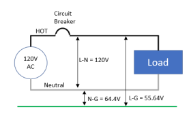
Without the N-G bond the 120V circuit is floating to some level that is independent of the ground circuit.
1635706888258.png
Notice that Vng + Vlg = Vln = 64.4 + 55.64 = 120.0


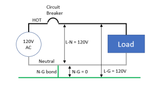
When there is an NG bond, the 120V circuit is 'anchored' to the potential of the ground wire.

1635707040405.png
As you can see, one of the purposes of the NG bond is to keep the circuit from floating to a potential different from ground.

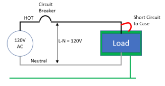
The second purpose of the N-G Bond is to 'clear a fault'. Imagine a scenario where there is a short between line and the grounded metal case of a piece of equipment. Without the N-G bond, there would be no current flow, the circuit breaker would not trip and the metal case would be 'hot'.

1635707712149.png
Also notice that even if the ground wire is tied to earth ground, the breaker will not pop.

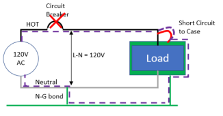
With an N-G bond, there is a low impedance path for the current to flow so the breaker will quickly pop and clear the fault

1635708167741.png
 
@FilterGuy
The test today DID NOT use the transfer switch panel, just direct to central vac (just used 12awg extension cord cut). Growatt was plugged in for UTIL tests to the same circuit as last night with GFCI and nothing popped today. The GFCI plug pop happened immediately last night when I tried connecting into the TS switch when on UTIL, even before I connected any load.

This is an indication the power circuit is floating and an N-G ground is needed. Does the 3 led circuit tester still show everything is OK?
When on battery using extension cord, still open ground. Open ground is not present when going through Transfer Swtich

Also, can you measure the current on the input cable ground?
Do you mean same measurements, but using the input ground vs the output ground?
 
@FilterGuy

On Grid UTIL Mode Output Cable:

Volts:
  • G/L1=120v
  • G/N=2.3v
  • L1/N=119v
This looks normal. The circuit is 'seeing' the NG ground that is in your house breaker panel. The 2.3V is the voltage drop on the neutral line due to the load (there might be some measurement error too). If you turn off the load, the 2.3V will probably drop to zero or a few millivolts.
Does this mean that UTIL IS working as expected? Wonder why my GFCI popped on UTIL and not on Battery when going through Transfer Switch last night.
 
Do you mean same measurements, but using the input ground vs the output ground?
yes
Does this mean that UTIL IS working as expected?
It indicates it is.


Wonder why my GFCI popped on UTIL and not on Battery when going through Transfer Switch last night.

It is hard to say... My *guess* is there is something in the wiring of the transfer switch (or downstream of the switch) that is creating an N-G bond.

Can you provide any kind of diagram of the wiring inside the transfer switch?
1635715772685.png
 
A couple more questions

1) Can you provide the exact model of the transfer switch? Is it one of the multi-circuit switches with the Grid-off-Gen switches?

2) Does the transfer switch feed into a breaker box? If so, is ground and neutral tied together in the breaker box?
 
@FilterGuy
The GFCI plug pop happened immediately last night when I tried connecting into the TS switch when on UTIL, even before I connected any load.
The circuit downstream of the GFCI does not need to be loaded for it trip on a neutral-ground fault. It's detected with no load.
 
A couple more questions

1) Can you provide the exact model of the transfer switch? Is it one of the multi-circuit switches with the Grid-off-Gen switches?

2) Does the transfer switch feed into a breaker box? If so, is ground and neutral tied together in the breaker box?
Had electrician do the work and inspection on TS install. Yes TS is connected in main panel where G/N is bonded. Here is the model. Instructions are in the link also.
 
The GFCI will pop with only 7mA (.007A). It would not take much of a load.
They trip on a downstream neutral-ground fault with zero load. My guess is that it's been that way for about 20 years. The best reference I can find quickly says at least 15 years. https://forums.mikeholt.com/threads/gfci-ground-neutral-fault-detection.2553469/

The video in the thread gives a reasonable description of how the Fairchild chip does it. Before that, the design was inject an equal 120 Hz, signal on hot and neutral. If there was a neutral-ground fault downstream, the 120 Hz signal would cause a current path between neutral and ground, creating an imbalance between neutral and hot, causing a trip.
 
Back
Top