Bluedog225
Texas
- Joined
- Nov 18, 2019
- Messages
- 2,908
I’d appreciate knowing or being pointed to a resource that explains the difference between a high and low frequency inverter? I’m trying to understand the pros and cons.
Thanks
Thanks


There are tons of details we could go into but it boils down to this:I’d appreciate knowing or being pointed to a resource that explains the difference between a high and low frequency inverter? I’m trying to understand the pros and cons.
Thanks
I have experience with only one of each, but based on that one experience, a low-frequency inverter can have a significantly higher if for draw and can put out much more heat when unloaded than a high-frequency inverter.I’d appreciate knowing or being pointed to a resource that explains the difference between a high and low frequency inverter? I’m trying to understand the pros and cons.
Thanks
There are tons of details we could go into but it boils down to this:
High-frequency inverters are generally lower-priced, lighter in weight, and can handle brief surges of 2x their wattage rating.
Low-frequency inverters are generally more expensive, weigh more, and can handle brief surges of 3x their wattage rating.

 diysolarforum.com
Funny, those are the precise two inverters I have experience with (Sigineer 6kW LF and WZRELB 3kW HF).A critical difference is the definition of brief.
My HF inverters can only handle a 2x surge for milliseconds. Not useful at all.
My Sigineer LF inverter can handle a 3x surge for 20 seconds. Enough time to start dual AC motors from locked status on a boat lift. Very useful.
Edit:
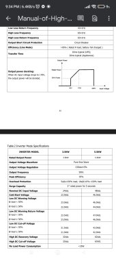
After reviewing my manuals I see that my 48v, 3000W WZRELB HF inverter can do 6000W for only 5 milliseconds.
My 48v, 3000W Sigineer LF inverter can do 9000W for 20 seconds.
That is a huge difference.
And the Sigineer was more expensive and weighs MUCH more weighing in at 53 pounds as opposed to 11 pounds for the HF inverter.
Here is a thread about when I bought the Sigineer:
Sigineer 48v inverter. 3kw, 120 ac
Anyone have experience with or a reasoned opinion on this inverter? https://www.sigineer.com/product/3000-watt-inverter-charger-48-volt-110v-120vac-pure-sine-wave/ The price is decent and I like that it can go up to 9000 watts for 20 seconds supposedly. I need to start/run dual 120v 3/4 HP...
That is certainly the reputation, but is that a fundamental difference between LF and HF? It could be that the low end of the LF market is trying to be as low price as possible and therefore are more likely to cut corners on the design and components. Are these units tarnishing the whole LF market? (I really don't know).Lifetime/reliability is an entirely different criterion, however, and HF inverters have the reputation of not lasting as long as LF inverters…
Hi @RCinFLA ,