diy solar

diy solar

Direct to water heating.

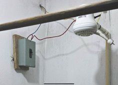
Here is one of my designs heating a house in northern Europe. I think he did an amazing job considering he has no previous electronic background. Please respect his privacy by not commenting.
 
Hello Hedges,

Mmm how i see it, but perhaps i'm wrong, if the inverter AC side is starving, i think it will instantly take power from batteries therefore keeping frequency at 60-61Hz. My inverter which is a chinese all in one, do that ... still i've never checked the variation of frequencies on the AC side.

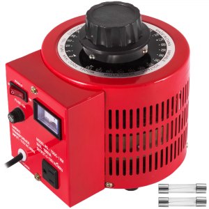
And.... the variac seems a pretty nice device, but i can't keep thinking that this thing is expensive ... :p

Battery inverter designed for AC coupling forms grid drawing from battery, but slews frequency up whenever it finds it has to suck down more power into battery than it wants to. Slews back down whenever it has to draw from battery. I think this behavior is somewhat like a generator loading down or spinning up. The inverter takes a couple seconds to do this, and has to support starting running loads from battery until PV inverter responds. It provides smooth management of distributed GT PV (or wind/hydro) inverters.

The variacs are usually $100 and up, but here's a 1kVA one for $56.
I got one for $25 or $30 at a surplus store that was clearing out inventory.


more typical, several hundred $$:


Everything I've got is expensive. Lab equipment probably a couple hundred $k MSRP but of course I didn't pay that. I try to get quality obsolete stuff with simple interface/language. I also scored some deals on brand new inverters.
 
Coincidentally, last week I ordered
I got lucky and found a new 50-gal water heater on Craiglist for $200. This will be a preheat tank feeding my existing water heater, which I will leave intact. I've been doing research and thinking on the pros and cons of different methods for a couple of months, and settled on this approach.

Selling points of this controller are the mppt, and that it rapidly switches the dc to simulate ac, to prevent arcing on the heater's thermostat contacts. It also has a settable temperature sensor which I don't think I'll need. I don't know when I'll start on the installation, but I will post the progress.
I just recived one of those controllers and am having a hard time thinking this thing can take 10 amps at 400volts. the wire connection points are so small and look cheap. have anyone installed one of these yet?
 
I just recived one of those controllers and am having a hard time thinking this thing can take 10 amps at 400volts. the wire connection points are so small and look cheap. have anyone installed one of these yet?
No I do not have one and this-
"PWM controller for heaters with the algorithm of searching for the maximum MPPT power point from photovoltaic panels.''
Doesn't enthuse desire to get one.
Maybe time to hit the refund panic button!
Edit- or cut your losses if you want a pwm cc with a temp sensor.
 
I'm switching to a heat-pump water heater soon and hope it will be easier to power with solar than a standard electric unit.
 
I'm switching to a heat-pump water heater soon and hope it will be easier to power with solar than a standard electric unit.
I have installed heat pump water heaters in my last two homes. It is much easier to power with a Grid Tie inverter. However, with rate changes, the last one I programmed to run during the day so it would use solar to store the heat. I only use full heat pump mode.
 
I just recived one of those controllers and am having a hard time thinking this thing can take 10 amps at 400volts. the wire connection points are so small and look cheap. have anyone installed one of these yet?

400V labeled on input, 10A labeled on output.
Possible.
The text then says PV max 10A.


No I do not have one and this-
"PWM controller for heaters with the algorithm of searching for the maximum MPPT power point from photovoltaic panels.''
Doesn't enthuse desire to get one.
Maybe time to hit the refund panic button!
Edit- or cut your losses if you want a pwm cc with a temp sensor.

"The regulator is supplemented with a buffer module containing capacitors, choke and diodes, which enables higher efficiency (up to 30%) and reduction of interference caused by PWM regulation."

If that "choke" is actually a power inductor, then PWM to the load would make it a switching power supply, and MPPT operation could be real.

If just an EMI filter choke, this can still do MPPT.
The way it works it PV panel delivers roughly constant current into roughly constant voltage capacitor bank.
Switch connects heater element to capacitor with PWM. Heater gets square wave between zero volts and Vmp (of panels).
That will maintain panel operation and maximum power point (given a decent algorithm which finds that operating point.)

Because this is a resistive load not a battery, it doesn't need to be a switching power supply buck converter to perform MPPT.

I think it is legit.
 
Do not use the output of the ACTii on mechanical thermostats. It is high frequency AC but it does not have arc interrupt. This is the reason for the temperature sensor.
 
Do not use the output of the ACTii on mechanical thermostats. It is high frequency AC but it does not have arc interrupt. This is the reason for the temperature sensor.

High frequency DC square wave?
Periods of zero current, but perhaps high frequency means not long enough for plasma of arc to go away.

Temperature sensor takes care of temperature regulation, but not over-temperature safety shutdown.
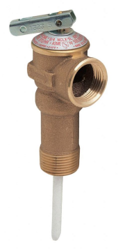
An electronic switch is likely to fail closed. Definitely have a functioning temperature/pressure relief (with pipe ducting discharge away from the face of people.) But I would also want a reliable way to cut off electrical power to heater. Maybe a crowbar circuit.

1641664589435.png 1641664613455.png
 
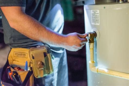
Everyone should replace the lower thermostat with an upper type which has the additional manual over temp. These may not keep working but they always work once. They are a double set of contacts which should be wired in series.

Not a big fan of preheat tanks unless the primary is rather small or there is very high use. Preheat tanks have a lot of heat loss once above 80F . Then the lower section of the primary tank is nothing but heat loss supported by the grid. Any reasonable array should be able keep it warm.

Without at least a month data on current electrical use, it will be difficult to view new data with any certainty of performance.
 
"The regulator is supplemented with a buffer module containing capacitors, choke and diodes, which enables higher efficiency (up to 30%) and reduction of interference caused by PWM regulation."

I think it is legit.
Until I see more substantive figures to prove otherwise, I am going to disagree.
The standard practice for DIY water heating is matching the panels with the element to get max heating capacity at full sun.
The actii maker agrees
Then double, in //, the number of panels to give some production in lesser sun. Or choose a element with 2 x R if doubling the panels is not an option.
There is no place in the mpp curve where a device can make up that difference gained by just doubling the panels when the load is fixed.

''The regulator is supplemented with a buffer module containing capacitors, choke and diodes, which enables higher efficiency (up to 30%)'' .....doubling the panels gives (up to 100%) !
 
When I was 14 I built a solar thermal panel for a science project. Pretty simple and cheap.

Maybe consider to pre-heat the water that way?

At one time, there was a company that made a combination solar PV and solar thermal all in one panel, but I think that they went out of business.
 
Would love to test an ACTii. For almost everyone here electronics is just magic and you can just keep making things smaller and smaller. Power electronics still takes considerable size. I always hated packaging a product. Never seemed fair that the box cost more than the electronics inside. The ACTii is packaged to ship easily. There just can't be that many capacitors inside. Like the techluck with three 100uF capacitors rated at 0.58A each and you want to dump 10A out of them. That will not be a long pulse and the ESR is going to kill the capacitors eventually. I heat water the same way and my capacitor bank is rated more than 20A and 20 times the capacitance. Just recently I connected with someone who had sung the praises of the techluck and now they ditched it because it became unreliable. Overall I think the ACTii is a pretty good design and probably will last 5 or more years. I don't really want anything I had 5 years ago. The control electronics looks really nice. It does require an isolated 12V supply and most cheap switchers will work well on over 100V DC. It does use an IGBT which by its very nature produces about 15W of heat at load. This unit was designed for the European market where heater watts are small and much higher voltages are needed. The photo booster module should be easy to repair and indeed improve with a more substantial capacitor bank. So, keep me in mind if you buy one.
 
That's exactly my situation. No one is home during the day. Most of our hot water use takes place in the evening. The solar is tied to the bottom element, the top element is still on grid but set 15 degrees cooler. I have generator hour meters to see how many hours the solar is working, and how many hours the top element is on. It's only been installed for a few months. But the numbers look encouraging...
I have the same setup but am using a 36 volt dc dual element in the bottom of the hot water heater. Half of the dual element is fed off of 3- 305 watt panels on the east side of my house and half of the element is fed off of 3- 305 watt panels on the west side of my house. Even with my wife being home now we are pretty well fed by solar unless we have a spell of cloudy days. The backup top AC 220 volt element has a timer wired into it so even if we do not have solar, it comes off and on on preset times as needed throughout the day. When the solar
 
I have the same setup but am using a 36 volt dc dual element in the bottom of the hot water heater. Half of the dual element is fed off of 3- 305 watt panels on the east side of my house and half of the element is fed off of 3- 305 watt panels on the west side of my house. Even with my wife being home now we are pretty well fed by solar unless we have a spell of cloudy days. The backup top AC 220 volt element has a timer wired into it so even if we do not have solar, it comes off and on on preset times as needed throughout the day. When the solar
You would be better connecting both arrays together into one heating element and monitoring the current to switch the second element on over a certain current.
 
I don't really want anything I had 5 years ago.

I don't really want to have to replace anything in 5 years.
My PV panels are 17 years old. Only reason I replaced the inverters is functionality (support grid-backup)
My youngest car just celebrated its 21st birthday. My oldest its 73rd.
My Daiwoo microwave made it to 21, then keeled over.
Refrigerator/freezers up to 24 years old (efficiency vs. reliability tradoff)
Gas Furnace about 25 years, electric duct heater about 20.
Water heater was at least 21 before it need to be replaced.
Fluke DMM around 20 years.
Bosch Brute 40+ years.
Honda Superhawk 57 years.
Youngest laptop 3 years, oldest 18 years.
I previously used cell phones for more than 5 years, but rate of change has increased and now cellular network keeps getting yanked out from under them.
PV and battery inverters I installed recently were > 5 years old, new old stock, and didn't need firmware updated.
Wife ... I'd better not go there.
 
This may help with some of the confusion of how PWM water heater controls work. The upper YELLOW scope trace is of only the AC portion of the capacitor bank which was sensed thru a capacitor to block the DC. The ramp up is the capacitor bank charging till it reaches the ON voltage. Ramp down is the heater turned on till it reaches the OFF voltage. This is only a few volts difference on the 120V array which at the time is producing 664W.

The lower GREEN trace is the FET turning on and off as measured at the drain of the mosfet. Low is zero volts indicating that the FET is turned on. The FET will turn on for a maximum of 10ms. This maximum corresponds to 50Hz. If after that time the capacitor bank has not reached the low turn off voltage, the FET will turn off for 0.64ms. This is the arc interrupt in action, see #1. Note #2 on the YELLOW trace which indicates the capacitor bank is recharging during this time.
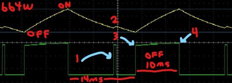
110Vripple664W_LI.jpg

Following the arc interrupt, the FET turns back on again for another 4 ms until the capacitor bank reaches the low turn OFF voltage #3. The FET then turns OFF for about 10ms (this time is not fixed) till the capacitor bank recharges again #4. Heating element is connected to positive of battery bank to drain of FET. Scope GREEN trace is inverse of what you normally expect of high being an on condition. ON is represented by a low state.

As stated before, the maximum ON time is never more than 10ms. That 10ms OFF time could be anything from 1ms to several hundred ms. The lower the light level, the longer it will be. The ON time can be as low as .5ms. It just can't be more than 10ms so any arc can be extinguished. Other manufacturers with smaller capacitor banks will have on times of far less than a quarter ms.

Point #3 shows the actual turn off voltage in relation to the zero voltage of the low GREEN trace. Point #4 is the turn on voltage. To be efficient you want this differential to be under 5%. Around the MPP voltage of the solar panel the power is relatively flat for several volts. Panels are current sources, and you want to maintain a constant current with as little fluctuation as possible. The capacitor bank must be large enough that the panel can keep dumping current into it in the off periods. If there is a wild fluctuation of current, then you are not harvesting all the power possible.

Some designs may use higher frequency, fixed or variable cycle times, arc interrupt or not. It all ends up as a PWM duty cycle. The voltage going to the element is always the same independent of light level as is the current. It is either on or off with only the duty cycle changing. A design can use a FET or IGBT as the output switch. IGBT were preferred for a long time when voltages were over 200V. The downside was when there were turned on there was always 1.5V to 2V across them when on. At full power that would be about 17W of heat which had to be dissipated. FET typically have very low on resistance and can produce little heat. Higher voltage FET in the past had much higher on resistance once you were over 100V. That increased resistance made the heat produced the same around 250V with the IGBT gaining an advantage. Today low resistance high voltage FET are not exotic. I use two FET in parallel which reduces the heat produces to one quarter of that of a single FET. An extra FET is a deal compared to having to use a fan and having extra cabinet heat. It is actually better than that because when a FET heats up its resistance can easily double, producing even more heat.

Selecting a heating element is the same as for direct connect. Find the rated MPP voltage listed on the panel and divide that by the panel MPP current (as long as that is under the controllers rating). What others won't mention is shade. Four panels in series is typical for resistive water heating systems. If two of those panels go into bypass a PWM MPPT controller will never give the true MPP of the array. That is because the heater element resistance would need to be half of that it was designed for. It would be perfectly fine to operate with this lower resistance with a controller designed for that. Most aren't because capacitor banks cost and are not small. I actually test mine with 45A pulses. The good news is this should typically, be a rare case. In fact, natural power point controllers (fixed voltage with temperature tracking) work almost as good on a daily basis.

I hope this explains solar PWM water heating.
 
Last edited:
Magick box 1 would be to series connect panels to make 240v to heat the element direct from panels. I would use a breaker and a fuse or 2 somewhere along the line.

I do not know if a heating element with a thermostat would work as I am not sure what the thermostat control will do with DC
i have done this for years. in the summer i get far more power than i need from a 200-300v string so i dump it straight into a water heater element.
where i live in europe you can buy $10 heating elements with long handle to put in a bucket or bath.
even that is overkill. a couple of carbon plates hanging in the water will do the job
 
Back
Top