diy solar

diy solar

Daly BMS Will Not Balance

but if you come to me for help I likely won't patronize you and understand you're just trying to learn like I am.
I am sorry, i was mostly trying to inject some humor, was not meaning to patronize.

I was just typing up a bit to inquire a bit about your charge controller settings. So you're on the same page with smoothJoey and I now.

So my 16s 310 pack is top balanced, or as balanced as I could get it.
First, how exactly did you top balance? Did you put all 16 cells in parallel and charge the pack to 3.65V or did you charge each cell to 3.65V?
Or something else?

Next,
"Battery boost charge voltage* is set to 57.6 by default. "battery floating charge voltage" is at 55.2 by default.
Good place to start!
57.6V / 16 = 3.6V. This is too high for day to day use. You're running at the redline. Check out this state of charge chart:
LiFePO4 SoC chart.png

To charge to 99% your charge voltage should be (13.4V x 4 =) 53.6V

But the real question is, at what voltage does your cell 7 really start to diverge from the others? THAT is roughly where you should be setting your top charge voltage if you cannot manage the cell balancing some other way.
 
My app is somewhat unreliable for current draw
Yea, BMSs and apps aren't really the most reliable sources of information about your battery. Looks like you have a good digital meter and know how to use it so i'd trust that information and not worry about what the BMS says (though i do hope the BMS itself has enough good info to know when to cutoff properly!)
 
my system is 48v everything is through a hybrid inverter, eco-worthy 3500
I am not familiar with this nor do i see any threads that go thru the settings.
Do you have it set to an LFP charge profile?
Can you post a screenshot or pic of the settings? With that, there are quite a few folks here that can suggest at least a good first pass at settings (subsequent passes may be necessary based on characteristics of your battery or usage).
 
First, how exactly did you top balance? Did you put all 16 cells in parallel and charge the pack to 3.65V or did you charge each cell to 3.65V?
Or something else?
Once confirming my studs were marked the correct polarity I initially tried in parallel with a starting pack voltage of 3.29, with one dc supply, 3.65v @ 5a and when the pack got to 3.36 or something it sat there for a few days without movement. I was then advised to put the pack into its 16s configuration, charge it with the hybrid inverter until the bms cut off charging to get the cells higher but still in a safe voltage, then break the pack apart and try in parallel again. I did that and then got a second dc supply and made 2 8p packs and with now 2 dc supplies and half my capacity I was able to get each individual 8p pack to 3.65 in a few days. Then broke them apart and put it back into my now 16s config.
57.6V / 16 = 3.6V. This is too high for day to day use. You're running at the redline. Check out this state of charge chart:
Remedied, thank you.
But the real question is, at what voltage does your cell 7 really start to diverge from the others? THAT is roughly where you should be setting your top charge voltage if you cannot manage the cell balancing some other way.
Once I sit and figure that out should I set the individual cell volt protect to where that starts to deviate or see what the pack voltage is at and set my top charge voltage too.
 
Do you have it set to an LFP charge profile?
Yes it offers fla, agm, and 14, 15 and 16s for lifepo4.

Can you post a screenshot or pic of the settings? With that, there are quite a few folks here that can suggest at least a good first pass at settings (subsequent passes may be necessary based on characteristics of your battery or usage).
Manual for mine and I think it covers some others.

 
Then broke them apart and put it back into my now 16s config.
Looks like a very good top charge, well done.

should I set the individual cell volt protect to where that starts to deviate or see what the pack voltage is at and set my top charge voltage too.
No, the cell protect (in the BMS is set to the 3.65V limit as always). You set the charge controller to stop charging at or just before a cell diverges.

In normal day to day use, if you can see where one cell starts to run away (like over 3.5V or 3.55V), THAT is where i would note the BATTERY voltage and set the top charge voltage (in the charge controller!!!) to stop there. In theory, you should get almost the entire capacity from your battery.

If you have a low voltage cutoff, using that same methodology to determine where that should be set works too.

The whole idea is that you want YOUR use case, including charging, to stay within the battery/cell safety limits governed by the BMS.
 
Manual for mine and I think it covers some others.

I see the settings in the manual and they seem pretty typical for default settings. Lets see if we can set it so that it
matches YOUR use case and your battery characteristics.

We have a handle on top charge voltage though yet to be determined where you see a cell going rogue during charge.

Next, i think YOUR use case makes a difference on many of the other settings, in particular float.

Is this for an RV or home that you are using 24/7/365? RV you use a couple times a month for the weekend? Months at a time?
 
Is this for an RV or home that you are using 24/7/365? RV you use a couple times a month for the weekend? Months at a time?
I read an acknowledge all the above thank you.
This is for my home to sit in standby essentially to use in case of a long-term power outage. It'll hook back up to my house through my interlock kit and once isolated from the grid run my home.
I have 1250 w of pv along with a predator 3K pure sine generator that would provide supplemental charging.
As of right now it really serves no purpose I just wanted to build one so I bought all the stuff and did.
 
to sit in standby essentially to use in case of a long-term power outage.
I have my system like that. It is "extension cord ready" to the fridge and freezer.

One suggestion would be to set the float below where the battery/cells settle within several hours. If the float is higher than where they settle, then the charger will micro-cycle: charge, settle, charge, settle, ... i suspect this is fairly hard on a battery and maybe SCC. Its certainly some unnecessary thrashing for a stand-by system.

My cells settle to around 3.35V per cell within a few minutes of full charge. I have my float at 3.32V. But in practice lately, i have been disconnecting solar and letting it sit until i gets below 3.3V (13.2V battery). So once a month or so i turn on the array switch for a day or two. Same with my RV, though that sits at around 13V (storage voltage, no state of readiness needed for power outage).

Here is a good thread with 48V system setting from a smart guy:
 
One suggestion would be to set the float below where the battery/cells settle within several hours. If the float is higher than where they settle, then the charger will micro-cycle: charge, settle, charge, settle, ... i suspect this is fairly hard on a battery and maybe SCC. Its certainly some unnecessary thrashing for a stand-by system.
So settled as in, once it's done charging on hook it from the hybrid inverter so it can't charge anymore and see where the voltages are at in a couple hours? If I leave it hooked up it'll eventually keep cycling like you mentioned below.
I have my system like that. It is "extension cord ready" to the fridge and freezer.

One suggestion would be to set the float below where the battery/cells settle within several hours. If the float is higher than where they settle, then the charger will micro-cycle: charge, settle, charge, settle, ... i suspect this is fairly hard on a battery and maybe SCC. Its certainly some unnecessary thrashing for a stand-by system.

My cells settle to around 3.35V per cell within a few minutes of full charge. I have my float at 3.32V. But in practice lately, i have been disconnecting solar and letting it sit until i gets below 3.3V (13.2V battery). So once a month or so i turn on the array switch for a day or two. Same with my RV, though that sits at around 13V (storage voltage, no state of readiness needed for power outage).

Here is a good thread with 48V system setting from a smart guy:
Ok thanks I'll give that a go over here shortly.
 
This is after letting it sit overnight with my charge and float voltage at 53.6.
I noticed when I came into my shop this morning the inverter wasn't flashing in charge like it has been. I think since I had my inverter charge setting higher than what the BMS would accept it kept trying to feed the batteries but the BMS stopped it.
So I go in turn on my app and the balance looks way better than it did the day before and it's not in charge mode.
I think later I'll sit and play with it and see where cell number seven or whichever one it is diverges and dial back the charge if I have to a little more but I think it's definitely an improvement from yesterday.
I don't know why I had it in my head that the absolute highest voltage possible was the best, but after reviewing your chart it seems as though like you said I was on the red line of being overcharged and to not stress over or try to get every cell up to 3.65.
And even here going off my lowest cell of 3.327 that times four gives me 13.3 which based on your chart above is 90%.
 

Attachments

  • Screenshot_20220104-101421_SMART BMS.jpg
    Screenshot_20220104-101421_SMART BMS.jpg
    151.8 KB · Views: 20
Hello boys following up on this a few days later.
With my updated settings I think it's keeping my pack balanced much better.
Although two pictures it is just one page from the app. This is after the hybrid inverter stopped charging it after I ran it down a little bit with a space heater.
You'll notice the soc on the app says 92%. I understand that's going off of the old SOC when I was overcharging. Since my burst and float voltage are now correct should I reset my SOC to be 100% now? Or am I not at 100% now with my battery voltage being 3.38 - 3.40.
Going off your handy chart above 3.40 per cell giving me 13.6 in a pack of four equals 100% but I wanted to be sure.
 

Attachments

  • Screenshot_20220106-163333_SMART BMS.jpg
    Screenshot_20220106-163333_SMART BMS.jpg
    167.8 KB · Views: 16
  • Screenshot_20220106-163329_SMART BMS.jpg
    Screenshot_20220106-163329_SMART BMS.jpg
    151.3 KB · Views: 16
Last edited:
The BMS "should" get better at estimating SoC after a few charge cycles. The BMS isn't really made to be an accurate capacity measurement tool so don't put much thought into that. If you really want/need to calculate SOC, then a shunt is needed; and even then they drift because they don't notice some small loads or account for self discharge. I stopped using my shunt because i had to do a sanity check against voltage anyway.

I consider 100% Soc to be where a battery settles within a few minutes after top charge. That's a good number to know.
You'll get a feel for it at a glance after a few charge cycles.

With my updated settings I think it's keeping my pack balanced much better.
That's remarkably good. Cell 16 (positive end of battery) may be powering the BMS so could explain difference.
Certainly not worth ANY worry .02V difference.

Here are some more finer grained charts:
 

Attachments

  • LFP Voltage Chart.jpg
    LFP Voltage Chart.jpg
    81.6 KB · Views: 14
The BMS "should" get better at estimating SoC after a few charge cycles. The BMS isn't really made to be an accurate capacity measurement tool so don't put much thought into that. If you really want/need to calculate SOC, then a shunt is needed; and even then they drift because they don't notice some small loads or account for self discharge. I stopped using my shunt because i had to do a sanity check against voltage anyway.
I think it did, I got a new 80a resettable breaker ( I know I could use a 100a but I'm just being over cautious since all this stuff was pretty expensive and I'd rather cut myself short on available power than risk something) plus I set my BMS to 80a max discharge so in my head it makes sense.
Anyway I disconnected from my hybrid inverter and put on my new breaker and I'm guessing that disconnect and connect was what the system needed to find its new soc because after the new one was put in the charger turned itself on and ran for about an hour at the 10a charge I have it set to and brought them here. Kind of weird the charger ran for a hour or so and the soc went up but voltage is pretty much where it was at last time with soc at 92% vs this now 99%. 53.3 was 92% and now 53.5 says 99%. It may have reached 100 but this was the last I checked it.
Certainly not worth ANY worry .02V difference.
Very good, thanks.
 

Attachments

  • Screenshot_20220109-133430_SMART BMS.jpg
    Screenshot_20220109-133430_SMART BMS.jpg
    168.4 KB · Views: 9
  • Screenshot_20220109-133434_SMART BMS.jpg
    Screenshot_20220109-133434_SMART BMS.jpg
    155.1 KB · Views: 9
Last edited:
Some more Daly BMS info:

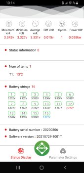
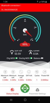
1- I discharged the battery by about 10% then set the balance voltage to initiate at 3.35V and the cell differential initiation to 0.001V. I then set the power supply to 2.5A (at anything below this, the balancing turns off). The current threshold for balance initiation is not adjustable in the Daly BMS. I then let it charge and the balance indicator light came came on when 3.35VPC and a differential of 0.010V was attained (not the 0.001V it was set for).. This was a good start, or so I thought.

2- Unfortunately the balance indicator then turned off after approx 11 seconds. Repeat, repeat, repeat. So, you need a minimum current flowing into the battery of about 2.5A and even when everything is set to balance, and initiate this at 3.35VPC & a 0.001V imbalance, the balancing is not consistent nor is it continuous. Balancing "takes a break" approx every 10 seconds to 30 seconds (not at all consistent). 10-30 Seconds ON, 10-30 Seconds OFF, repeat, repeat, repeat. The longest duration I have measured balancing remaining ON is 59 seconds, but again, not consistent and no rhyme or reason as to why it is an ON/OFF behavior? It is typicall ON/OFF between 10 & 30 seconds.....?

3- I tried to re-program the zero amperage calibration and it will not stick. The minute you go back into the app, after programming the preferences, the change is wiped out. Thus no way I have found to override the 2 - 2.5A balance threshold for current (this also is not consistent).

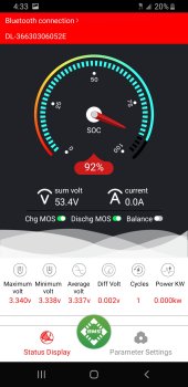
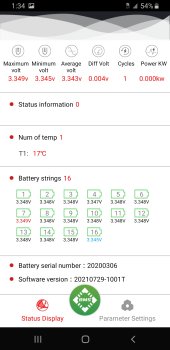
4- This morning, at approx 14.25V (manufacturer recommended charge voltage 14.4V), after charging at 2.5A, the SoC was way off reading 76% SoC. This was with 14.25V at the terminals and 0.00A flowing into the battery (14.25V is a full battery and the Charge FETs were on and the battery accepting 0.00A. The following cell voltages were observed.
3.463V
3.687V
3.389V
3.706V
14.245V / Pack

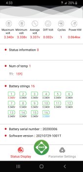
5-
I am back at it now with a delta voltage of 0.176V and balancing set to initiate at 3.32V and a 0.001V cell to cell differential, with 2.89A flowing into the cells. Balancing won't initiate at all. This Daly BMS seems to have a mind of its own? Settings changes seem to be a "feel good" measure only. By the settings and amperage this BMS should be balancing, based on the accepted settings (yes, the BMS has saved them) and it's not. It is the job of a BMS to balance cells.

This Daly BMS is the biggest cluster I've yet to see in any BMS. I've been doing custom built LiFePO4 since 2008 so not at all green at this. No matter what I have tried, this Daly BMS cannot and will not balance these 100Ah cells.

I am hoping someone has the answer because this is ridiculous, especially if this is how it is designed to operate. Oh, and apparently every-time you reset/re-program the app the cycle counter goes back to 0.......

How on Earth does Will rate this as a good BMS?
I am having the same issues. Second time charging the cells (12V 4S) and the balancing function turns on at will. One of the cells is falling short on voltage 3,35V instead of 3,65V. I have seen the balancing function working sometimes, it switches on for seconds, but now it won't which means I can not charge my battery further than 89% SOC. I will try discharging the battery a bit and recharge to see If the balancing fixes the issue but so far this is a very disappointing experience. How can such sophisticated BMS have no continuous balancing function even If at low current?
 
One of the cells is falling short on voltage 3,35V instead of 3,65V.
If I've learned anything here from the two sorcerers above that gave me a lot of info is that there's really not much difference between 3.35 and 3.65. I used to think there was and was hung up on making each battery 3.65 but if you look at the chart above 3.35 will give you a pack that is 99% charged and 3.65 might seem like a big difference but it's 1% more and as someone told me about that's pushing it as far as overcharging.

it switches on for seconds, but now it won't which means I can not charge my battery further than 89% SOC
Mine does the same thing, daly 16s 150a smart BMS. I was using that for SOC when I was trying to make each battery 3.65 and had a huge different voltage like you seem to have.


How can such sophisticated BMS have no continuous balancing function even If at low current?
I don't really think there's an answer other than it just doesn't, those wires are literally the thinnest wires available before it becomes non-existent it probably can't even handle the advertised balance current.

I forgot what my initial differential voltage was when I came to this thread but it wasn't great and now if you look at my last picture it's something super low like 002.

The first thing was making sure I was actually top balanced so I shut my charger off and let the battery settle and they quickly fell into that point 002 or 3 area indicating that I was top balance it was only when I tried to essentially overcharge the pack they would get out of balance.

This is my pack just this morning.
When you do a test on yours and use it a bit and then the charger picks back up and starts charging what stops the charging? The charger or the bms? For me it was the BMS which was wrong the entire time as I learned about the BMS should not play a role really in normal use unless of course you go over under voltage. My pack was 100% when I was trying to overcharge them and then once I fixed the settings on my charger to have it not try to shove so much current into the batteries my new SOC was 92 compared to my old 100 after three or four days the system fixed itself and now stays right here at 99 and if you do the math of my voltages 3.35 * 12 and then * 4 I'm at 99% which matches my SOC. In short I think you're trying to bring the battery voltages too high. I would shut your charger off and have no load and check your BMS app after a little while and see what they said a lot it's probably balanced and if they're not balanced balance them before going any further.
 

Attachments

  • Screenshot_20220114-065046_SMART BMS.jpg
    Screenshot_20220114-065046_SMART BMS.jpg
    170 KB · Views: 8
Last edited:
If I've learned anything here from the two sorcerers above that gave me a lot of info is that there's really not much difference between 3.35 and 3.65. I used to think there was and was hung up on making each battery 3.65 but if you look at the chart above 3.35 will give you a pack that is 99% charged and 3.65 might seem like a big difference but it's 1% more and as someone told me about that's pushing it as far as overcharging.


Mine does the same thing, daly 16s 150a smart BMS. I was using that for SOC when I was trying to make each battery 3.65 and had a huge different voltage like you seem to have.


I don't really think there's an answer other than it just doesn't, those wires are literally the thinnest wires available before it becomes non-existent it probably can't even handle the advertised balance current.

I forgot what my initial differential voltage was when I came to this thread but it wasn't great and now if you look at my last picture it's something super low like 002.

The first thing was making sure I was actually top balanced so I shut my charger off and let the battery settle and they quickly fell into that point 002 or 3 area indicating that I was top balance it was only when I tried to essentially overcharge the pack they would get out of balance.

This is my pack just this morning.
When you do a test on yours and use it a bit and then the charger picks back up and starts charging what stops the charging? The charger or the bms? For me it was the BMS which was wrong the entire time as I learned about the BMS should not play a role really in normal use unless of course you go over under voltage. My pack was 100% when I was trying to overcharge them and then once I fixed the settings on my charger to have it not try to shove so much current into the batteries my new SOC was 92 compared to my old 100 after three or four days the system fixed itself and now stays right here at 99 and if you do the math of my voltages 3.35 * 12 and then * 4 I'm at 99% which matches my SOC. In short I think you're trying to bring the battery voltages too high. I would shut your charger off and have no load and check your BMS app after a little while and see what they said a lot it's probably balanced and if they're not balanced balance them before going any further.
Thank you very much for your extended and carefully written answer. It gives me huge peace of mind honestly; having a battery with unusable capacity would kill me, but that is not the case.

Actually new things happened. I have charged the 4S LifePo4 12V 60Ah battery with 2A charger for 24h; battery stopped charging due to voltage cell 3 & 4 reached 3,7V. At that moment voltage difference was 0,3V and SOC was 90%. I have given the battery 2 hours rest; voltage difference went down to 0,07V. I have reconnected the charger hoping the balance function would have enough room to correct the voltage differences. It did not; it charged the battery for 30 seconds until cell 3 & 4 reached again 3,70V (voltage difference 0,25V) and stopped, but close to that moment the SOC jumped from 90% to100% in one go.

Conclusion; drink more beer, micromanage less my battery. It will be fine.
 
Last edited:
battery stopped charging due to voltage cell 3 & 4 reached 3,7V.
Where is your BMS? It should disconnect at 3.65V every time. Every time.
Your battery's parachute (BMS) is set to open after you hit the ground.

At that moment voltage difference was 0,3V and SOC was 90%.
How are you determining 90% SoC?
What are the voltages of the 4 cells?
Conclusion; drink more beer, micromanage less my battery. It will be fine.
Words of wisdom. But you still need a BMS and SCC set properly.
 
3 & 4 reached 3,7V
Too high, unless you have different cells than I do. If you can put a picture of you app like mine above that shows the 4 cells.
I have given the battery 2 hours rest; voltage difference went down to 0,07V.
They're only going astray when being charged because there is too much current trying to get shoved into the battery bank.

Whether you have a hybrid inverter like I do or all separate components, the charger should be stopping the charging not the bms.
 
Where is your BMS? It should disconnect at 3.65V every time. Every time.
Your battery's parachute (BMS) is set to open after you hit the ground.


How are you determining 90% SoC?
What are the voltages of the 4 cells?

Words of wisdom. But you still need a BMS and SCC set properly.
Too high, unless you have different cells than I do. If you can put a picture of you app like mine above that shows the 4 cells.

They're only going astray when being charged because there is too much current trying to get shoved into the battery bank.

Whether you have a hybrid inverter like I do or all separate components, the charger should be stopping the charging not the bms.

Answering you both. First some information:
- I have a 14,6V 2A LifePo4 low-cost charger from Aliexpress. The charger stops charging as soon as total battery voltage reaches 14,6V and won't resume charge unless I disconnect it and plug it in with a battery voltage below 14,6V.
- The battery is protected with a Daly smart BMS 60A that I still hope is appropriate for a 60Ah battery.
- The Daly BMS stops charge not because of the total voltage reaching 14,6V but because one or two cells reach the maximum voltage. The app default setting for high cell voltage was 3,75V and I have changed it to 3,70V. Following your comments I will probably lower it to 3,65V.

Then here you see a screenshot of my Daly smart BMS app shortly after finishing the first 24h charge. Charging was stopped by the BMS due to high cell voltage (>3,7V).
1642409227509.jpeg

Second, a screenshot of the final state of the battery following the story of my previous email. Unfortunately you can't see the cell voltages but these were very similar to the voltages in the first screenshot with the exception of cell 1 and 2 which were both just 0,03V higher; reason for which voltage difference is slightly lower compared to the first screenshot.

The story from the previous email: Actually new things happened. I have charged the 4S LifePo4 12V 60Ah battery with 2A charger for 24h; battery stopped charging due to voltage cell 3 & 4 reached 3,7V. At that moment voltage difference was 0,3V and SOC was 90%. I have given the battery 2 hours rest; voltage difference went down to 0,07V. I have reconnected the charger hoping the balance function would have enough room to correct the voltage differences. It did not; it charged the battery for 30 seconds until cell 3 & 4 reached again 3,70V (voltage difference 0,25V) and stopped, but close to that moment the SOC jumped from 90% to100% in one go.

1642409303739.jpeg

Thank you for your interest and feedback.
 
Back
Top