


Lionking45
New Member
- Joined
- Jan 18, 2022
- Messages
- 8
Posting this to solicit feedback on any flaws in my logic
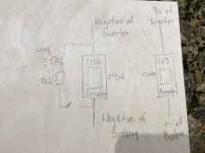
My idea is to create a switched parallel circuit to the circuit breaker on the negative leg from the battery to the inverter. There is a lamp and a 20 ohm resistor in this parallel circuit. This parallel circuit is initially open. The main negative breaker is open. The positive breaker side is closed I will then close the switch to bypass the breaker and allow current to pass through but the current is limited by the resistance in the resistor and the lamp. As the voltage in the capacitor builds up, the lamp will turn off as the voltage differences between the battery and the inverter capacitors equalize and go to zero. I will then confirm the voltage through a meter and only then close the negative breaker. I will open the switch on the parallel circuit before I close the breaker.
Thanks for any input.
Ariel
")