diy solar

diy solar

Deye / Solark 8K Setup, Some photos an diagrams!

Hi great thread , I’m having the same issue f-20 . I checked the panel polarity before connecting to inverter and it was correct. But while wiring tonight I learned the hard way about backfeed . The panels were disconnected but the deye was on . While wiring in the pv to the mppt I got bit bad . Took me a while to find where it is coming from but from ground ( case of inverter ) to any mppt input ( pos or neg) I have 244 vdc . My arm is still hurting it hit me so hard . Why does the input have a voltage 244 vdc lower than the case ? Seems like rsd would be worthless because the inverter would backfeed

I think the Deye, if similar to Sol-Ark, has a high voltage DC rail. PV feeds high voltage rail from which AC is made (rather than conversion first to battery voltage), battery is boosted to same high voltage rail, or charged from it. For models which AC couple, AC also goes to high voltage DC before charging battery. Likely AC line input does too.

I would expect a separate PV connection with MPPT circuit charging that rail, and not backfed, but maybe not?
As you note, RSD boxes between panels can't do anything about voltage on wires from inverter. Although, if RSD is activated by inverter, that may discharge those wires.

Working on my GT PV inverters, after disconnecting AC and DC I have to wait a while for capacitors to discharge on DC side. That is much slower than RSD requirement, so would require additional circuitry or operation of inverter into a load.

One Deye I looked up specs for accepts 100 to 500V input. The circuit would be buck/boost to work around 244VDC.
Although there is a diode in buck-boost topology, it might leak to charge up capacitor.


Now you know to check all voltages with meter before working on it.
 
Good to know when im playing with my conections. Great explanation as usual Hedges.
 
mrdavvv,
I am going to install my Deye 8k in a few months and wondered how loud the fans were? (what noise level would you compare them to?) You said earlier that they were loud and the temperature setting for them seemed less than ideal. Did you have any luck with better fan control or perhaps changing them to quieter fans?

TIA,

Kid
 
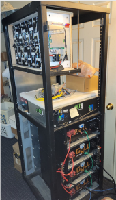
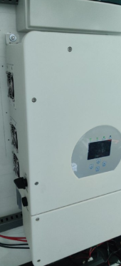
So this beast finally arrived:

View attachment 36504View attachment 36505

View attachment 36510

(8K LP1 US model) -- At a first glance i really like the quality of materials and the weight of it!.

  • Planning on putting 10.5Kw of panels (26 x 405W), in a east - west configuration. Panels would be around 20 - 30° to E / W.
  • Each MPPT would have 2 strings in parallel, with 6 or 7 panels each.


View attachment 36506


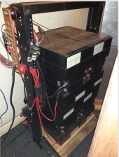
Also bought a little pylontech battery (2.2Kwh@48V), it should be able to communicate with the inverter trough CAN / RS485, this is against the DIY spirit ;).... but didn't have the 2 months to wait for the lifepo4 cells to arrive:

View attachment 36507

This would be the diagram of the full installation

Full Image Link
  • What do you think?, any mistakes in the drawings?, any recommendations?.
Ill keep posting here with updates during installation.
Way, Way to small Battery, I started off with 51.2v - 200ah and now have 51.2v 1002 ah, makes all the differents.
I don't feed the Grid, just the Garage, Joe.
 
mrdavvv,
I am going to install my Deye 8k in a few months and wondered how loud the fans were? (what noise level would you compare them to?) You said earlier that they were loud and the temperature setting for them seemed less than ideal. Did you have any luck with better fan control or perhaps changing them to quieter fans?

TIA,

Kid

They are very loud and spin very fast, around 5000rpm i believe, so its kind of high pitched noise. I havent had time but it should be relatively simple to connect the fans to a PC fan controller and make then spin all the time to 3000rpm or something similar, or even attach a temp sensor in there.... Just not sure if the inverter will try error codes for that, but im guessing you can place a resistor or something instead of the fans to fool it.

Way, Way to small Battery, I started off with 51.2v - 200ah and now have 51.2v 1002 ah, makes all the differents.
I don't feed the Grid, just the Garage, Joe.

Since then i updated to 150ah, but its fine for me as the main circuit its fed from the grid, and the 24/7 never shutdown loads are around 500W.

Can i see that battery?
 
Thanks for the info. I may try mounting fans on the intake side and pushing air through with my own control.
Another option might be to replace the factory fans with quieter fans that still produce enough airflow. But I think controlling the airflow externally will work better.
I will update when i attempt this, but it will be May before I can start my project again. (had to return home to do the job thing)

Kid
 
Yeah please update, you are probably doing it before me.

Not sure if the inverter uses PWM or straight voltage, but either way i dont think there is silent fans at 80mm and >4000 - 5000rpm's, so the fan controller its probably a safer bet.
 
They are very loud and spin very fast, around 5000rpm i believe, so its kind of high pitched noise. I havent had time but it should be relatively simple to connect the fans to a PC fan controller and make then spin all the time to 3000rpm or something similar, or even attach a temp sensor in there.... Just not sure if the inverter will try error codes for that, but im guessing you can place a resistor or something instead of the fans to fool it.


Since then i updated to 150ah, but its fine for me as the main circuit its fed from the grid, and the 24/7 never shutdown loads are around 500W.

Can i see that battery?

51.2v 800ah ------------------------------------------------------------------------200ah started out with al Lifepo4
1641879855812.png 1641879912959.png
 
Sure!.

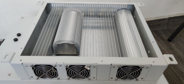
From a front view, the 3 left fans are injectors, they force air in.

1649278873052.png

And the exhaust its at the right side (With no fans, only grilles)
 
Thanks so much for your reply. My Deye 8k is 700 miles away and I can't just look in the box for these answers.
This info will help me start planning a forced air system to try to keep it from kicking on the factory installed fans.

Kid
 
Thanks so much for your reply. My Deye 8k is 700 miles away and I can't just look in the box for these answers.
This info will help me start planning a forced air system to try to keep it from kicking on the factory installed fans.

Kid
I wouldn't force cooled air directly into the inverter.
It's better to condition the space it's in. And let it do what it does. You don't want to create condensation inside the inverter.
 
The room is humidity controlled. (basement) So I am not concerned with condensation. Also I do not think a running inverter in an inside space would reach dew point temperatures. (even with venturi effect)
Kid
 
The great thing about this inverter design is that the heat disipation its entirely in its own sub unit / enclosure. No electronics aside from the fans. They are only connected by some big aluminum heatsinks:

1649302370652.png

I have my inverter inside an AC controlled space. But the whole PV system is less efficient because of this, since part of the energy produced its wasted keeping the room cool. The inverter its probably 50% of the heat gain from that space.

I was wondering if i could run some air ducts directly from another area into the inverter, and same with the exhaust; thus keeping the unit ventilated but with little heat gain on the AC controlled room. While helping to keep the inverter cool with the enclosure in nice 26°c temps.

But didnt think about the possible condensation problems. The air passing trough the heatsink area could be +5-8c hotter.... but the air inside the electronics area has very low humidity (because of the AC), so not sure about it.

Its probably not worth the effort / risk.

Im interested in your solution when you have a design or photos @kid744
 
I am still a few months away from being able to assemble my system. (work obligations)
But I will definitely post my failure/success in helping cool the Deye.
(keeping the loud factory fans from needing to run.)
There may be a simpler solution, such as replacing the factory fans or asking Deye to change the cooling profile in firmware.
But I intend to explore the less invasive options first.
Thanks to all for their valued suggestions/concerns.

Kid
 
Hi, thanks for the great info all. I have 2 of the Deye 7.6 KW units, not hooked up yet. I am trying to figure out the best system design.

So the plan is to run the two units in Parallel mostly on-grid (with zero export to utility). I have 20kWh (400AH) of batteries and 6KW of DC coupled solar (to start), hoping to at least double the solar and batteries eventually. My house has 2 - 200 AMP main panels with 200 AMP bus bars, (plus a few sub panels off of each of these) with loads pretty balanced between both panels and phases. The 2 main panels are by no means maxed out and are overkill for current loads, but I wanted to have space for future electric load expansion.

My utility has a TOU tarriff so my primary goals are to avoid using grid power during the peak 12-6pm period as much as possible, generally offset as much usage as I can with solar+battery, and have backup in grid-down scenarios which happen a few times a year in my area (lots of old trees in area)

It seems that the simplest way to connect the inverters to my house panels would be to feed the "Grid" in/out from the inverter into my main panel at the bottom (opposite end from main 200 amp breaker, put the "Load "outputs into the same panel at the top with an interlock so utility main has to be off to turn on 'Load' breaker during grid-down. I realize this requires manual intervention during grid-down, but I'm ok with that. I can also manage my loads during grid-down, so I don't think I need a critical loads panel. Am I understanding this correctly?

I realize I am also ignoring the Paralleling of the two inverters and two main panels situation. My understanding is I will need two new AC combiner panels, one to combine the "Grid" in/out for each inverter and the other to combine the "Load" out for each inverter. I will then run conductors from each of those combiner panels to each of my main panels as described above.

I'm trying to figure out proper breaker sizing for the "grid" and "load" breakers going into the main panels (and in the AC combiners). To comply with the 120% rule I assume I will need to derate the 200 AMP breaker, altough reading through these forums, it seems like there is little possibllity that the 200 AMP bus would ever see 200 AMPs if the backfed "grid" breaker is at the bottom.

Sorry for the long post and noob questions! Thank you in advance
 
I have a couple of thoughts about this.
On the issue of condensation, it is easy to visualize the risk if you think about your aluminum drink can. It is wet when the can is cold but not when the can is warm. Seems simple but it helps to see it. We want to avoid cold surfaces and warm moist air with a dew point higher than the surface temperature of our beloved electronics and stuff. Our electronics tend to be warm so it is less of an issue but never forget that sometimes in uncontrolled environments there will be cold spells where things cool down followed by an influx of warmer moister air when the weather shifts. During those times the objects that are still cold will condense moisture out of that newly arrived moist air. That is how a lot of corrosion occurs. I prefer to keep my expensive systems in climate controlled space that is built to be energy efficient.

The efficiency of the batteries and inverters is improved by keeping them in friendly temperature and humidity conditions and the durability of the components will be dramatically improved as well.

That is why I build energy efficient enclosures and use energy efficient air conditioning systems to heat and cool those enclosures. Thermal mass can also help moderate the temps and the energy required to maintain the conditions we want.

I have videos about this on my channel. They aren't the more popular videos but in my opinion they are the most important to our success long term, uhhh ok, it all matters actually but this stuff should not be overlooked or brushed aside. We only usually get one chance to get it right. Buy once, cry once.

Yeah makes sense. But wich part of the wall condense the water?. I believe its the hotter side?. Moisture or condensation occurs when a hotter / moist air comes in contact with a relatively colder surface. So in that case, the condensation will occur in the heat sink area of the inverter, wich doesnt have electronics. aside from the fans. Probably not good for the steel surface but they have good electrostatic paint and 80% of the material there is aluminum or something with rust protection.

Im talking about keeping the deye in the cold environment, and only suck / exhaust air from "outside" trough its ventilation module.

What do you think?
There may be a simpler solution, such as replacing the factory fans or asking Deye to change the cooling profile in firmware.
But I intend to explore the less invasive options first.
Thanks to all for their valued suggestions/concerns.

The fans are very annoying and loud. My first solution its just put a PWM controller from a PC, and run them at 20 - 40% all the time But interesting in knowing your ideas once implemented.
 
My concern was on the electronics side. If the heat sinks temperature were to get low enough.
Probably a long shot, for this to happen. But, I tend to think very far into the what if category.
I think ducting the exhaust to the outside is a good idea. That could even incorporate a low volume fan, Probably. It could even be controlled by the temperature of the heat sinks. That way it would take the place of the noisy fans. And, they could still operate as a backup function.
 
Well it looks like the Mrs. is going to insist on the inverter being installed in the carport utility room rather than the basement.
This will add to the length of some of my wiring runs. 8^(
Not sure if you answered this in the original noise question portion of this thread, but did you notice any inverter humm when the unit was operating? Not sure if reports of such noise are more common to HF inverters from Deye.
I am still going to attempt to find a better cooling solution so I will update when I get that in place. (still 2.5 months away from install)
@mrdavvv When you had your cooling section apart did you notice what voltage and possibly model number the cooling fans were?
If they are 12 VDC, that would make replacing them with quieter fans a definite option. We could also bolt on 80mm x 120mm adapters to the outside if they are 12VDC.
TIA,
Kid
 
Back
Top