diy solar

diy solar

Direct to water heating.

Is there any off-the-shelf stuff you guys know about that one could set up a mess of solar panels and magic box 1 and maybe a magic box 2 and directly drive a 240V 4,800W standard water heater element?

Any ideas welcome.
All of you members … you need to seriously do your homework… I don’t want to hear in the news how experimenters flowing themselves or houses up. The thermostat and control boxes in a hot water heater are AC devices not DC …when you put DC through contacts you create a large arc and run the risk of welding the contacts together and don’t have any control of the devices anymore. You potentially may create a bomb inside your hot water heater, turning water to pressurized steam . The heating elements don’t care AC or DC .. they are purely resistive devices .. using AC you get a more uniform dermal distribution than DC but they still work. If you are only making hot water and nothing else put in a solar absorber and go sunlight to hot water, more efficient .
 
I spent a lot of time this past winter trying the same thing. The problem I ran into is that the low resistance of the heating element pulls the voltage down so low, there is not much power coming from the panels until midday. I found reasonable success with a dc-to-dc boost converter. It takes 20-60 VDC, and converts it to 120 VDC. Of course, it is pulsed DC, but the element doesn't care about that. The best part is you can use the existing thermostat without burning out the contacts. I started to build one, but then I found one on EBay for 25 bucks delivered. I used 2- 250 watt 72 cell modules in parallel. Was putting 4A @ 120 VDC into a 1000 watt / 120 VAC element. Works fine. Those modules are still available. Just search 900w DC-DC boost converter.
Is this the boost converter you used?

 
All of you members … you need to seriously do your homework… I don’t want to hear in the news how experimenters flowing themselves or houses up. The thermostat and control boxes in a hot water heater are AC devices not DC …when you put DC through contacts you create a large arc and run the risk of welding the contacts together and don’t have any control of the devices anymore. You potentially may create a bomb inside your hot water heater, turning water to pressurized steam . The heating elements don’t care AC or DC .. they are purely resistive devices .. using AC you get a more uniform dermal distribution than DC but they still work. If you are only making hot water and nothing else put in a solar absorber and go sunlight to hot water, more efficient .
very good advice. in my country we use un pressurised boilers. arcing with dc can be a real issue with ac rated switches and thermostats. use only gear rated 3x your dc voltage minimum. best idea is use a solid state relay or mosfet. a capacitor across switch contacts also works but again it needs a good rating. all pressurised boilers MUST have a blow off valve whatever means you use to heat them.
boiler explosions devastate brick and concrete buildings. i dare not imagine what they do to american stick houses.
dc can be safe if used correctly, measure your voltage carefully on and off load, adjust string length as needed.
in europe there is a big online market for used industrial frameless panels generally 80-160w 80-120v per panel. i buy them for about 120 euro per pallet of 20-30 so its cheap enough not to worry about mppt. i also prefer the price of thin household cable instead of 100a copper busbars.
i assume that by dermal distribution you mean that parts of the element that are in colder water are lower resistance? i will do a check on that with an exposed element and flir thermal camera. im not expecting to see anything major.

is anyone else extensively using DC here?
 
Is this the boost converter you used?

Using a boost converter is generally a real goofy idea. I understand the appeal to those who have no understanding of electronics. A boost converter tries to regulate its output. That forces the input voltage lower and lower as boost converter tries to substitute more current for less voltage. This spirals the panel down to lower less efficient operation in low light levels. Boost converters can be modified to keep panel voltage at near the power point voltage. Even then, these boost converters are inefficient with the resulting gain in power barely worth it.
 
Never heard about that. As long as the heating element is isolated from Water and only resistive, there is absolutely no performance difference between AC and DC.
But as said, DC could be an issue for electromechanical thermostats.
I have no reference for what I am about to say... but I thought that DC was actually more efficient on purely resistive heat loads than AC due to the fact that AC cycles and drop to zero while crossing over in the sine wave. DC being not a wave form simply inputs x amount of energy per time unit. As a result AC actually imparts less energy over a time span. once again i am not an electrician, just curious. if wrong can somebody explain the errors in my thought process?
 
if wrong can somebody explain the errors in my thought process?
In AC, the current and voltage is measured in what is known as 'Root-means-Squared.' This is a complicated mathematic way of measuring AC current and voltage in 'DC equivalent' numbers when using a resistive load. If you look at a 120V AC signal on an oscilloscope, the voltage peaks are at 170V.

Note Root-Means-Squared can be thought of as the average..... but it is not really an average. The mathematical average of an AC voltage or current is zero.


The net result is that if you have 100V going through a 100-ohm resister it results in 1 amp regardless of AC or DC. It also burns 100W in both AC and DC.

However, When the load is inductive or capacitive, the equivalency starts breaking down.
 
The net result is that if you have 100V going through a 100-ohm resister it results in 1 amp regardless of AC or DC. It also burns 100W in both AC and DC.

However, When the load is inductive or capacitive, the equivalency starts breaking down.

It also breaks down when only current is a sine wave, and voltage is DC. It works for AC source.
Battery current ripples when feeding a single (or split-phase) inverter. It wouldn't ripple feeding a 3-phase inverter, or DC loads.
For power delivered by a battery, you need to use "mean" average current. For heating of wires and fuses (and transistors), you have to use "RMS" average current.
That's because delivered power is (battery) voltage X current, but self-heating of components is current X current X resistance.

I've found the published efficiency specs of inverter follow pretty close to no-load power plus some constant multiplied by current squared. That's likely the self-heating of inductors and MOSFETs.
 
The net result is that if you have 100V going through a 100-ohm resister it results in 1 amp regardless of AC or DC. It also burns 100W in both AC and DC.
From memory that is what they wanted back in the day, AC & DC having the same energy, when they set the standard for AC measurement and upon realising rms was close enough they took that opportunity and made it the standard of measurement....the Current Wars ??
 
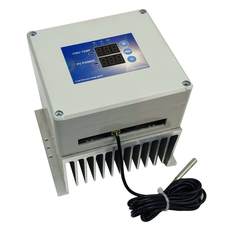
Thanks guys, after reading this thread I took a look at the actii module and saw they have a new version out that is contained in one box and does not need an external power supply. I purchased one and have been running it for the past month. 1600 watts of panels into a 300 litre tank and most days the water temperature is at 50 to 60 DegC and has been up to 85 DegC. I am in Ireland and we do not get that much sun. It has worked flawlessly, its well built and I've had no issues at all. The only thing is that it went out of stock shortly after I purchased. I imagine these being highly desirable with the gas supply issues in Europe now.

 
Fascinating, thanks for the update, and get back to us in a year with further update if you can.
 
Thanks guys, after reading this thread I took a look at the actii module and saw they have a new version out that is contained in one box and does not need an external power supply. I purchased one and have been running it for the past month. 1600 watts of panels into a 300 litre tank and most days the water temperature is at 50 to 60 DegC and has been up to 85 DegC. I am in Ireland and we do not get that much sun. It has worked flawlessly, its well built and I've had no issues at all. The only thing is that it went out of stock shortly after I purchased. I imagine these being highly desirable with the gas supply issues in Europe now.

I am just wondering, as an engineer, how these guys would perform a true MPPT without any coil in their electronics?
 
MPPT charger has a DC output. The direct water heater has a square wave output. The MPPT tracking here is to have such a duty cycle on the transistor, that the capacitor voltage * duty cycle has the highest value. Or something like that. I haven't thought much about the math behind it, but the idea is kind of clear.
 
Last edited:
That is a much improved design over the first one eliminating the fan and external power supply. It still doesn't have arc interrupt which would allow heaters to be daisy chained using mechanical contacts. Thermally stratified tanks are the way to go with PV so the top of tank can heat quickly. It sounds like they eliminated the fixed power point option which allows this to be used in parallel with a charge controller. Or, this could just be a bad translation. No, you do not need inductors to do efficient MPPT water heating. A few more capacitors would be nicer.
 
That is a much improved design over the first one eliminating the fan and external power supply. It still doesn't have arc interrupt which would allow heaters to be daisy chained using mechanical contacts. Thermally stratified tanks are the way to go with PV so the top of tank can heat quickly. It sounds like they eliminated the fixed power point option which allows this to be used in parallel with a charge controller. Or, this could just be a bad translation. No, you do not need inductors to do efficient MPPT water heating. A few more capacitors would be nicer.
watching this intently and hoping....if two or three of these could be used with a quality MPPT in tandem this would be the cats meow/
 
MPPT charger has a DC output. The direct water heater has a square wave output. The MPPT tracking here is to have such a duty cycle on the transistor, that the capacitor voltage * duty cycle has the highest value. Or something like that. I haven't thought much about the math behind it, but the idea is kind of clear.
No.
A real MPPT needs a way to convert the input couple current/voltage into another couple current/voltage so to get more current at the output, that you have got at the input.
Only chopping PWM, without storage in a coil, will never permit this.
You will always be limited to the maximum current that your panels can deliver.

You will imperatively need a MPP voltage of the panel system to be close to the voltage of the boiler to get acceptable results.
On the other side, having an overall efficiency of 20% with a real MPPT or having an overall efficiency of 18% without won't make so much difference neither.
It will always be much worse, than vacuum tubes.

Another thing to clarify is: does the square output have a null mean value to eliminate galvanic problems?
 
Last edited:
No.
A real MPPT needs a way to convert the input couple current/voltage into another couple current/voltage so to get more current at the output, that you have got at the input.
Only chopping PWM, without storage in a coil, will never permit this.
You will always be limited to the maximum current that your panels can deliver.

Correct that maximum (average) current to resistance water heater will equal maximum current from PV panels.
Incorrect that this can't be a real MPPT.

PWM between capacitor bank and resistive load varies power draw. If capacitor bank is held at Vmp (plus a small ripple), PV panels operate at maximum power point.

During PWM, of course current to heating element toggles between zero and V/R. Peak current of course will be higher than PV Imp. Mean current will equal Imp. Power will be I^2R x duty ratio.

It can provide maximum power point tracking.
 
It can provide maximum power point tracking.
OK. It can provide some kind of MPPT, with the power stored into the capacitors.
The advantage being that you must not match any minimum output voltage as if you were constrained by a battery system.

But you will have to use a panel systems MPP voltage close to the boiler's nominal AC voltage to run optimally.
 
You just need Vmp from PV to be equal or higher than voltage required (at 100% on) for heating element to use 100% of power.
If Vmp is higher, then PWM has less than 100% on time.
Heating of transistors during switching transition is a penalty, especially if heatsinked to air. Switching at lower frequency would reduce power dissipated in transistors but increase capacitor ripple voltage, so could deviate from Vmp. Larger capacitor could fix that.
Hope the controller has temperature sensors and adjusts operation to protect itself.
 
Even a volt or two won't be a ripple that would reduce much the power. If you have 300Vmp then 3V would be 0.5% less power (this is ripple and the half is 1.5V) than the maximum one. If you add the voltage drop on the transistor you would still be close (or even above) the efficiency of most MPPT SCCs.

And they have a decent heatsink. If the transistors are fast and are properly driven there won't be issues with dissipated heat.
 
Last edited:
Back
Top