diy solar

diy solar

Cinergi's 28 kWh / 4 kW Solar / 10 kW inverter RV build

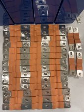
Looks like nickel plated copper to my eye. I believe the base material is nickel plated copper which is stamped to shape, then they are stacked, and the heat shrink is applied. So the edges will be bare copper.

Given how flexible they are, hopefully surface imperfections will flatten out with pressure. You could also use a press/vise/hammer/anvil to flatten them out.

It may be possible to take the heat shrink off, and swap the top two/three layers to find a smoother one?

Certainly seems that way. I just used an emery board to fix the two highly imperfect ones and polished everything with a dremel & wheel. They look to be in pretty good shape now. Despite how much material I took off, it's still plated (I didn't reach copper). Much thicker plating than my current bus bars.

You're probably right about rearranging the layers; I do have a vise to recompress everything but I don't think I'd get it right.
 
You're probably right about rearranging the layers; I do have a vise to re compress everything but I don't think I'd get it right.
I looked into making (DIY) this style bus bar a while back. I concluded I could buy them for quite a bit less than I could make them so I never did it, but I learned a lot as I was looking into it.

My guess is that If you try to rearrange the layers you are likely to mess things up.

If these are like the ones I have looked at, they are compressed into a cold weld at each hole. Getting them apart would be difficult to do without ruining them. Furthermore, you would probably not be able to re-establish a cold weld with just a vice. It is going to take a pretty powerful press.

The other thing is that each layer is a slightly different length. With them laid out with the hump up, the bottom one is the shortest. The next layer up has to hump up just a bit more to go over the hump of the bottom one so it is a tiny bit longer.... and so on. If you rearranged the layers they will not fit together properly.
 
My meter isn't sensitive enough ... or perhaps I don't know how to use it lol. Reads 0.0 Ohms. Klein CL800
Assuming you're using the meter right and assuming it isnt capable of the low resistance measurement that should be that size copper conductor (whatever it is), I would venture to say its real copper. There's a thread on here by @RayfromTX where he determined some of his busbars were not copper based on the resistance measurement. He probably knows the details off-hand.
 
I looked into making (DIY) this style bus bar a while back. I concluded I could buy them for quite a bit less than I could make them so I never did it, but I learned a lot as I was looking into it.

My guess is that If you try to rearrange the layers you are likely to mess things up.

If these are like the ones I have looked at, they are compressed into a cold weld at each hole. Getting them apart would be difficult to do without ruining them. Furthermore, you would probably not be able to re-establish a cold weld with just a vice. It is going to take a pretty powerful press.

The other thing is that each layer is a slightly different length. With them laid out with the hump up, the bottom one is the shortest. The next layer up has to hump up just a bit more to go over the hump of the bottom one so it is a tiny bit longer.... and so on. If you rearranged the layers they will not fit together properly.

Thanks! You've reinforced my own "I'll probably screw it up" thoughts with the detailed "why" part which makes perfect sense.
 
New bus bars installed.

At 17 amps with old bus bars, I saw a 0.3mv drop across the long bus bars. With the new ones, it was 0.5mv. Expected - these aren't nearly as much copper. But I'd have to think they're copper based on how they're performing. I have no concerns there.

I charged and let the battery balance to 10mv and then drew it down to 93%. I then charged from shore power at max (120 amps at 56 volts, over 6000 watts), and everything remained cold. The Orion BMS cell voltage graph looked excellent and I had no runners as the battery reached full. Orion cell resistances all looked great, too. This was a great initial test - and a good test to make sure my parallel connections were good (otherwise I would have runners). So I'm happy with the bus bars. We'll see how things fare over the next few days and months...
 
On a separate note, it's been over 1 year since I put this into commission. The Orion BMS tracks the total # of pack cycles (a "cycle" is the sum of Ah discharged & charged - 2x the Ah rating - so for me, 1080 Ah on a 540 Ah pack). I never reset that number, so it includes all the testing I did during the build. I'm at 257 cycles. At a 4,000 cycle "lifespan" that's 15 years.

I'm sort of accidentally doing a capacity test now because I'm running the mini-split heat during a cold & rainy period right now. I'm down to 39% and falling. I'm gonna configure the Quattro's to connect to shore just before they shut down due to low voltage, maybe 47 volts (2.94 vpc) and I'll see what the consumed Ah is etc. Hopefully very close to 540 :)
 
New bus bars installed.

At 17 amps with old bus bars, I saw a 0.3mv drop across the long bus bars. With the new ones, it was 0.5mv. Expected - these aren't nearly as much copper. But I'd have to think they're copper based on how they're performing. I have no concerns there.

I charged and let the battery balance to 10mv and then drew it down to 93%. I then charged from shore power at max (120 amps at 56 volts, over 6000 watts), and everything remained cold. The Orion BMS cell voltage graph looked excellent and I had no runners as the battery reached full. Orion cell resistances all looked great, too. This was a great initial test - and a good test to make sure my parallel connections were good (otherwise I would have runners). So I'm happy with the bus bars. We'll see how things fare over the next few days and months...
good going. 120A with minimal heating, sounds satisfyingly like a win for the day.
 
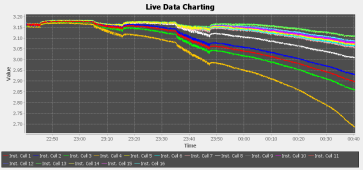
8% - 50.7 volts. Some serious divergence started ... at 60mv now. In theory I should still have another 43Ah left. I doubt I'll get that far. And I don't know that I performed a capacity test using the BMS to measure the Ah so this isn't really apples-to-apples. I tested each cell using a CBA IV tester and my lowest cell was 270 so I set the pack capacity to 540 (since I'm in a 2p config).

1654140104079.png
 
8.4Ah left and I've got a cell-pair below 2.7 volts. Pack voltage is 48.2. I've configured it to connect to shore at 48v. Assuming the BMS calculation is the same as the CBA IV tester I used, I'm at 98.5% of my original capacity (likely higher). I now also know what pack voltage to use for inverter shutdown that will safely keep me away from that particular runner.

This has also had a nice side-effect from a testing standpoint of making my cells contract and expand their maximum amount, putting the new busbars to the test.

1654144835455.png
 
8.4Ah left and I've got a cell-pair below 2.7 volts. Pack voltage is 48.2. I've configured it to connect to shore at 48v. Assuming the BMS calculation is the same as the CBA IV tester I used, I'm at 98.5% of my original capacity (likely higher). I now also know what pack voltage to use for inverter shutdown that will safely keep me away from that particular runner.

This has also had a nice side-effect from a testing standpoint of making my cells contract and expand their maximum amount, putting the new busbars to the test.

View attachment 96882
Any more updates? Curious to hear the final result.
 
Any more updates? Curious to hear the final result.

It connected to shore at around 2.65v (nearly 400mv of deviation - expected, given I have cells that tested to 270Ah and others at 281) so 98.5% (probably higher due to my testing methods here) of my original capacity 1 year ago.
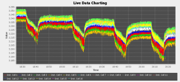
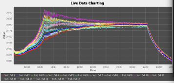
I got it fully charged about an hour ago. 125mv of deviation at the top and it balanced to 10mv in 70 minutes. All cell resistances look great (meaning my new bus bars are holding up despite the contraction & expansion). I disconnected from shore at roughly 19:40 in the graph below.

1654214431418.png
 
Thanks for the data, very useful!

A couple questions, I tried wading through the thread, but gave up after 10 pages. What is your charge voltage? How many months/years has the pack been in service?

The reason I ask, is so that I can work out your degradation a function of pack age and cycles.
 
Thanks for the data, very useful!

A couple questions, I tried wading through the thread, but gave up after 10 pages. What is your charge voltage? How many months/years has the pack been in service?

The reason I ask, is so that I can work out your degradation a function of pack age and cycles.

Absorb *and* float is 56v. I'm generally at that voltage less than 4 hours a day. Pack is just over a year in service. About 260 cycles. It was operating in elevated temps (over 90F) for < 1 month. Temps never got below 40F. Charge amperage max per cell is < 40 amps (.15C). Discharge max is similar.
 
1% per year while cycling is very good, Though your temps aren't southwest like, which helps. Assuming a standard capacity loss acceleration, 15 years should be totally doable, maybe 17 if you don't mind operating with capacity less than 80%.

My vans pack has seen more elevated temperatures, and its been about 18 months, so you may have motivated me to do a capacity test.
 
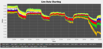
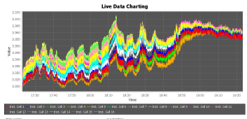
There's a funny temporary 30mv cell divergence around the 60% SoC mark - always happens whether during charge or discharge. First time I've noticed it (because I've been hanging around 35-70% SoC the past few days due to clouds). Always fine (<5mv) before 60% and fine (<5mv) after roughly 65%. No balancing is occurring at the voltages - it's just an interesting difference in the curve around this spot.

1654557836964.png
 
Back
Top