diy solar

diy solar

Heltec (JK) 200A Smart BMS with 2A Active Balance

Yes. currently "hacked" both together using two 6AWG crimp on connections to a short 4AWG..

View attachment 96415


I only had the display with switch. I ordered the BMS on April 20th.
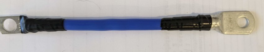
I'll be doing exactly the same for my "P-" pair. My placement of BMS (above the cell tops) allows both of the supplied wires to reach the "B-" battery lug without creating a jumper. This photo shows one of the 7-AWG "B-" wires, with my "better terminal lug attached (smaller hole, bigger surface area for the lug itself). That should be adequate for my needs, although I could upgrade to much larger "plain copper threaded wires in place of these small ones.
 

Attachments

  • B- 7-AWG battery jumper with better lug.jpg
    B- 7-AWG battery jumper with better lug.jpg
    93.6 KB · Views: 34
Last edited:
Does anyone have a US source of big silicone insulated wire? Something that does not take a month to get?
 
I had ordered some off of ebay, only took about a week to get.. you could also try a car audio place, they sell heavy flexible cables as well for car amps..
 
Does anyone have a US source of big silicone insulated wire? Something that does not take a month to get?
the silicone insulated wire i have gotten from vendor "bntechgo" on amazon has been pretty decent.
e.g. 8awg, 6awg :

more sources welcome, they don't seem to offer anything bigger than 6awg.
 
I used "Windy Nation" #2 and 2/0 cables off of Amazon. Got that wire in just a few days.
They have bundles with the matching lugs and heat shrink
 
I used "Windy Nation" #2 and 2/0 cables off of Amazon. Got that wire in just a few days.
They have bundles with the matching lugs and heat shrink
Thanks. That looks like 105C EPDB and not silicone but would be a good alternate choice.
 
View attachment 96170

Got my JK BMS recently. It had some extra gear which as I understand it should be able to start the BMS without a battery. Not sure if it’s worth using, have anyone tested it? Seen any YTers try it?

I do have the same JK BMS. This seems to by a HW Version 10.XG. So far I can't find any manual for the pinout of the small connectors under the balance leads.

Does anybody know the pinout of the RS485 connector and what's the small connectors under the bms leads?

THX
 
Yes. currently "hacked" both together using two 6AWG crimp on connections to a short 4AWG..

View attachment 96415


I only had the display with switch. I ordered the BMS on April 20th.
I used a switch outlet box to protect the BMS dual connections to the larger 1/0 cable to the battery. One large bolt ties it together. The other side is connected through a shunt.1654092596525.png
 
I do have the same JK BMS. This seems to by a HW Version 10.XG. So far I can't find any manual for the pinout of the small connectors under the balance leads.

Does anybody know the pinout of the RS485 connector and what's the small connectors under the bms leads?

THX
I have a couple of these in a box somewhere. I dont need them anymore, so can send them to you if you ping me with your address. (I am moving, so I need to find them in the miriad boxes i have been packing though) i believe I ordered these from Heltec.
1654092924591.png
 
I have a couple of these in a box somewhere. I dont need them anymore, so can send them to you if you ping me with your address. (I am moving, so I need to find them in the miriad boxes i have been packing though) i believe I ordered these from Heltec.
View attachment 96750
I bought this with my BMS. BUT: The Socket doesn't fit in the CAN/RS485 socekt. Only in the GPS Socket :rolleyes: This is the reason I'm asking for a update manual...
 
I bought this with my BMS. BUT: The Socket doesn't fit in the CAN/RS485 socekt. Only in the GPS Socket :rolleyes: This is the reason I'm asking for a update manual...
Since you want to live dangerously :giggle: here are links for the Development Software and Doco trees on github. USE AT YOUR OWN RISK!

Instructions:https://github.com/NEEY-electronic/JK/tree/JK-BMS

BMS protocol to connect to other devices:https://github.com/syssi/esphome-jk-bms

VenusOS driver:https://github.com/Louisvdw/dbus-serialbattery

I found this: https://diysolarforum.com/threads/jk-jikong-rs485-interface-wiring.35071/post-442064

An the esphome jk bms github shows a direkt wireing of the RS485 -> I'll give try.
 
Is there a specific order the cables from the BMS should be connected? I had some odd readings over my battery switch when connecting it…

 
I first attached the temp Sensors to different battery cells. I then attached "B-" power leads from the battery pack "-" terminal of the first cell in the pack.

After verifying in-order cell voltages on the balance+power pins at the balancing header port (my 4S-8S unit uses only one port balance/power port connection), I connected that header. I connected "P-" leads to my common grounding bus. As my final step, I plugged in the small GUI monitor and activated the unit via push-button. (It can also be activated by providing "charger" voltage to the battery pack).

If you have "odd readings", your cell terminal posts are possibly loose (if not welded in), or the nut on one of the individual cell terminal post wasn't torqued correctly. It's possibly that you did a poor connection on one of the balancing lead terminal rings, although that is an unlikely source of error.
- - -
Your other Thread's last photo shows the "B-" twin links going into some kind of switching component, on their way to the 16S pack's lowest cell "-" lug. That is utterly, totally wrong. They should merely be jointed to a single larger cable, with NO interfering switches or electronic components. If you want to "blow" $10 to make it look pretty, this one would do a great job: https://smile.amazon.com/LEIGESAUDIO-Copper-Gauge-Distribution-Splitter/dp/B07D1JLN8N

Thanks!

1. I got some different inputs on the order of the BMS and the SmartShunt. Someone looking at the a diagram of my built before starting said something like 'I got me SmartShunt after the BMS, but either way will work", and I think Andy was discussing the same thing.

Should I change it? My thinking -- that could be totally wrong -- was that the BMS was getting its reading's from the cables on the busbar and after that only functions as a relay basically, being able to shut down the battery, and that it was beneficial to have the smartshunt and its reading's as close to the source as possible everything else equal.

But I think that could be a misstake (which I assume is what you are saying), because as it is now, the SmartShunt is working even with the BMS turned off -- which means that if the BMS disconnects the battery due to low voltage, the SmartShunt will keep drawing current from it which can't be good, right? I mean, I recon the Smart Shunt don't draw much, but if its on for months it should struggle. Because the SmartShunt can't turn off itself, can it??

2. After I connected all cables from the BMS, i.e. also the battery minus, I couldn't replicate the odd reading I got. There must have been current flowing backwards through the BMS cables in some odd way. Physically nothing else seem possible unless I am missing something.

I assume that you definitely should connect all BMS cables before inserting the BMS cable terminal into the BMS which I had not done.

Anyway, I will continue that part of it in the thread linked to above.
The shunt measures current by putting a small portion through a resistor, the rest through the bypass portion. It has significantly higher resistance than the plain par of copper cords (JDK-supplied or other highly stranded cable). It should be connected as the first component on the "P-" leads.
 
The shunt measures current by putting a small portion through a resistor, the rest through the bypass portion. It has significantly higher resistance than the plain par of copper cords (JDK-supplied or other highly stranded cable). It should be connected as the first component on the "P-" leads.
perhaps a mistaken understanding,

doesn't all the current go through the sense resistor?
 
I worded that badly, or I misunderstand myself: The measuring components of the "Shunt" device cannot handle the full capacity which the device is designed to take. Nearly all the current on my Coulomb Counter goes through a low-resistance casting, while only a tiny portion goes through the higher-resistance measuring components.
 
Back
Top