You are using an out of date browser. It may not display this or other websites correctly.
You should upgrade or use an alternative browser.
You should upgrade or use an alternative browser.
Solar house generator I started DIY back in 2000 - My path from Trace to Xantrex (on FLA battery) to XW Pro inverters on Tesla Model S batteries
- Thread starter dougbert
- Start date
Hedges
I See Electromagnetic Fields!
- Joined
- Mar 28, 2020
- Messages
- 20,535
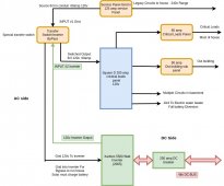
"120V Inverter Output"
Do you convert that to 120/240V split phase?
Issues with delivering just 120V to a split-phase panel, must be dealt with appropriately to avoid brown-out to some devices, or overloading shared neutral white wire of some circuits.
Your "special transfer switch" is shown with more than the usual 2 inputs, 1 output. Is inverter able to sit between grid and load panel, acting as a UPS?
dougbert
Solar Addict
I run only 120v circuits on my critical loads panel, no 240v since I only have a 120v inverter at the moment
my critical service panel, 200 amp Square D, has 120v on both sides of the panel and follow a protocol to only install 120v circuits
(this will change when I upgrade to the 240v inverter)
my only 240v loads in the house are the range and un-used electric dryer socket.
these circuits are in the original grid service panel
Only the range is powered and runs only on grid all the time
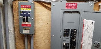
below are pics of the Inverter Bypass switch I bought in the late 90s
Square D QO load panel. The builder of it in california, I don't think is in busy any longer
Primary critical loads panel on the right
on the left is the Inverter Bypass with an interlock toggle
Close up of the front panel
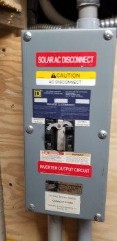
Interior pics, multiple to get pics of the wiring diagram inside
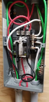
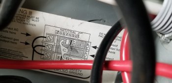
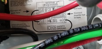
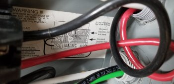
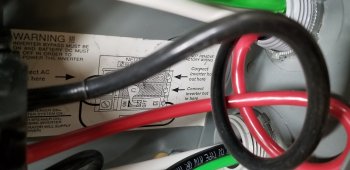
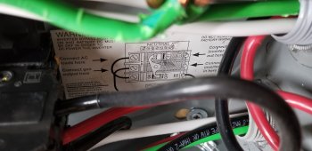
my critical service panel, 200 amp Square D, has 120v on both sides of the panel and follow a protocol to only install 120v circuits
(this will change when I upgrade to the 240v inverter)
my only 240v loads in the house are the range and un-used electric dryer socket.
these circuits are in the original grid service panel
Only the range is powered and runs only on grid all the time
below are pics of the Inverter Bypass switch I bought in the late 90s
Square D QO load panel. The builder of it in california, I don't think is in busy any longer
Primary critical loads panel on the right
on the left is the Inverter Bypass with an interlock toggle

Close up of the front panel

Interior pics, multiple to get pics of the wiring diagram inside


Last edited:
dougbert
Solar Addict
"120V Inverter Output"
Do you convert that to 120/240V split phase?
no, only 120v
Issues with delivering just 120V to a split-phase panel, must be dealt with appropriately to avoid brown-out to some devices, or overloading shared neutral white wire of some circuits.
120v only on service panel
Your "special transfer switch" is shown with more than the usual 2 inputs, 1 output.
Has 120v circuits
1) Grid Input - from L1 from original grid service panel
2) Grid Output - pass through to Inverter Grid Input to allow for invert bypass when batteries are below Cut off voltage
3) Switched Input 1 - from grid # 1 above
4) Switched Input 2 - from Inverter output
5) Output to Service Panel
Is inverter able to sit between grid and load panel, acting as a UPS?
Yes
dougbert
Solar Addict
well only 1 L1 leg 120v going to transfer switch - it what was available 22 years ago, still works todayOK, so you do have 120/240 split phase going through transfer switch to 200A panel as drawing shows, but it was loaded for compatibility with 120V inverter feeding both busbars.
when I get the 15kw 240v inverter, I won't be using that transfer switch at all.
I will document the next plan later
Nobodybusiness
Collecting the leftovers of the Great Sky Reactor.
I got interested in Solar from Richard Perez and his wife Karen.
Will, I love your energy of spirit and what you have done, researched and how you teach it is great.
When I build things, I generate a build log of what, how , where, when, who, why questions and answers for that build so that I can have a diary of you will of what I did.
This pattern I have used on rebuilding my trucks, one of which is shown in my avatar
So I am sharing this log of my system (currently on my local computer) here so it can used for reference by myself and others:
This was ALL DIY by myself
I began my interest in solar power generation back in 1993 time frame when I came across an issue of the HomePower magazine. I subscribed and received all future issues til the last one that went out in November 2018. An archive of them is located at www.homepower.com
At that time I could not buy solar equipment due to cash flow. BUT I could work on reducing my loads in my house. I counted 50 incandescent 60 watt light bulbs located throughout the house. One by one I replaced them all with 13 watt CFL bulbs ($20 each) - I stored the old bulbs so when we moved I would put them back - which I did and took all the CFL bulbs with me.
I measured consumption via the electric meter for the months before and after I swapped out the bulbs: Power consumption went down 30%
I learned of and bought a load meter for individual devices, but it was expensive $100+. Eventually I learned of the Kill-A-Watt for $25 and have used that ever since.
With such metering devices I measured all the pluggable devices in the house. I insulated the refrigerator (floor coils) not side cooler and gained a reduction there.
My first purchase was an 18 watt Chinese panel for $150, back in 1996 time frame. I also purchased a Trace 10amp charge controller for $120. - I still have this controller. We had an old 1 car garage that is really just a large shed, in which I setup this system.
Starting car battery
18 watt panel
10amp charge controller
wires
switch
and a single 12v light in the shed
No other meters, just the above
Of course I got the usually wife "What do you want to do?" questions and looks so I kept my mouth shut mostly.
Then one night the grid went down and I was not home. My wife went looking for some kind of flashlight and one place she went looking was the shed. As she entered, she just flicked the light on and went looking............(wait for it)...............then she realized that the grid was down (I had taken the old grid light out) but she had lights! She finally saw the vision, er the Light.
SOME FOUNDATION
There are 4 major components in any power generating system:
1) Generation
2) Processing
3) Storage
4) Loads - or things that consume electricity - the WHY we like electricity
I too was subscribed to the magazine.
It was fun reading all the articles.
It just wasn’t viable for current residential homes then.
Price per watt was about $5.
dougbert
Solar Addict
I just bought module #11, it is waiting for its partnerNice to see you posting again Doug.
I have been researching and designing for a new 240v inverter, but have been learning much on various threads and resources on this website
issues on common neutral and inverter bypass operations, along with N=G bonding
sticky issues
Hi Doug
Happy to report that I invested in a small (3) Tesla battery system.
Set up is only temporary while we are building our retirement home. So far works great and haven't had to turn on the genny for 3 weeks now.
System is 8x 320PV, Sigineer 24v 6000w tesla compatable inverter, Midnite DC panel and Midnite charge controller.
Have 3 to 8 guys working with me using 2 tablesaws, air compressor with up to 3 nail guns, chop saws and misc skill saws and Hilti drill.
Inverter has been able to keep up so super happy with the progress and no more dino fuel to build the house.
Fuel up here is CDN $1.98 L. for the low grade, over 4500 hrs on the genny......
Ordered 3 more batteries from the guy that you sent me the link to.
Thanks for posting and your help.
dougbert
Solar Addict
I finally kicked off Phase 3 with my system
After researching the new AIO units out there, I just ordered a Growatt 12kw LF inverter as my new inverter for doing 240v
My goals are:
1) Being able to "handle" the Low Voltage Disconnect of the Tesla batteries. Well, at least lower than other inverters. I have had my batteries LVD currently at 38.6 volts. The 12kw can do 40.0 volts. So I do lose 1.4 volts of capacity on the low end, but I accept that now
2) Be a single unit, not 2 (like the EG4 6.5k inverters), as I don't have space for it
3) be 12kw or greater
4) be cheaper than the Sigineer
5) have better digital monitoring
6) Have US based support - good reviews for Signature Solar
7) Be capable of supporting new tech batteries (like the EG4 and others)
So I am refactoring parts of my system now to support 240v, like pulling new L2 6 gauge wire from here to there, replacing the 120v transfer switch by putting in the 3 pole 240v Transfer switch, bumping upto 80 amp breakers and cleaning up things.
this will support my wife's range (I would have installed a gas range, but she hates gas ranges), and once installed will place the house at 100% stand alone operation, with the system having grid assist for charging on those days when the battery is depleted. Due to monsoon storms in August, I had 2 days where the LVD kicked in for a few hours. Before that, last December LVD events occurred about half of the month due some heavy snow storms. I only produced 51% of my power that month and had to buy the rest. Was glad it was available.
Beyond that, more solar panels to be add and more batteries modules added over time to reach the goal of not needing the grid at all.
My design pattern for my system started 22 years ago, and can be seen by physical layout it is today. If I started today my system would be simpler but due to invested 12 year old designs of the Schneider charge controllers, my system is bigger physically than newer tech would accomplish
Still tinkering and having fun with this productive interest and hobby. It is so rewarding to see just how far the solar tech has proceeded, along with the features we have today compared to 10 and 20 years ago. It's wonderful
PS, will need to consider selling the 5.5kw Xantrex inverter I got back in 2020, or save it. It is 2005 model and I got it due to the fact it could handle the lower LVD. Got it for $2000 then. I wish the Growatt was available then and I knew about, I should have gotten it then. I know people bought them in 2021
Wish the firmware for the Growatt 12kw could handle 38 volt LVD - then I would be truly in heaven. Well maybe
Last edited:
dougbert
Solar Addict
Spent the day re-factoring the AC wiring getting ready for 240v inverter
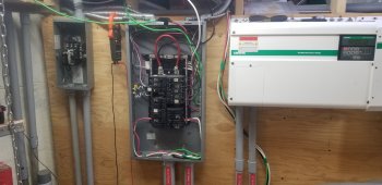
Here "was" the 120v transfer switch on the left and the solar critical sub panel setup to be run by the inverter. Jerryrig the feed line from inverter to panel for temporary service for a day or two.
lncoming grid is disconnected and about to be torn down and rebuilt
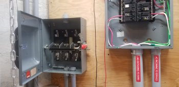
On the left is the 3 pole double throw transfer switch. Grid source from top, inverter source from bottom, Outgoing taps in the center feed the critical loads panel. Got this switch from ebay last year, just been waiting for this
Just screwed to the wall awaiting wires

Here is the incoming grid sub panel. Breaker on left will feed down to the transfer switch for sourcing grid AC, thereby by passing the inverter so it could be worked on
Middle breaker will feed out to the right and down to raceway and then into the inverter for inverter "AC IN"
right breaker is extra, not used at the moment, but filling in the front panel
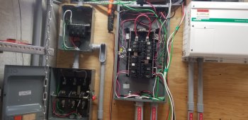
Here on the left is partial wiring setup
I had to shut the power off to the house totally in order to properly set up the critical panel for temporary powering. Had to schedule with wife to shut things down, and when ready, she took a nap.
The inverter AC IN and AC OUT (hanging down) will be split apart from that bundle and AC IN (ground, L1 and new L2 to be put in and neutral) will be installed in the conduit leaving the grid panel on the right and down to the raceway then to the inverter
AC OUT (L1, new L2 and neutral) will come up from the raceway and enter the bottom of the transfer switch and be connected to the lower 3 taps. Ground from inverter to critical panel will NOT be installed, as a ground (following along side AC IN, to the raceway and then up to the critical panel) from grid panel to critical loads panel will be separately installed to prevent ground loops
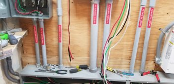
There is an undocumented/unexplained operation on the N-G bonding during AC Grid Passthrough and the manufacturers do not explain nor document the issue.
Below are some links talking about this
I am switching neutral with the transfer switch, but neutral is IN COMMON on this 120v only inverter (2 white neutrals in the bundle)
For new 240v inverter, this setup will allow me to:
either setup for
Switching neutral
OR configure for a COMMON neutral with relative ease
Researching the issue in the following thread

 diysolarforum.com
Another thread talking about this issue

 diysolarforum.com
another thread

 diysolarforum.com
FilterGuy made a great post here

 diysolarforum.com
here is a great PDF the FilterGuy made and uploaded.
"This document shows diagrams for proper grounding and bonding of either the MPP LV6548 or the EG4 6500EX-48 for several common scenarios."

 diysolarforum.com
Growatt confirms the following transformer model:
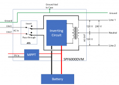

 diysolarforum.com

Here "was" the 120v transfer switch on the left and the solar critical sub panel setup to be run by the inverter. Jerryrig the feed line from inverter to panel for temporary service for a day or two.
lncoming grid is disconnected and about to be torn down and rebuilt

On the left is the 3 pole double throw transfer switch. Grid source from top, inverter source from bottom, Outgoing taps in the center feed the critical loads panel. Got this switch from ebay last year, just been waiting for this
Just screwed to the wall awaiting wires

Here is the incoming grid sub panel. Breaker on left will feed down to the transfer switch for sourcing grid AC, thereby by passing the inverter so it could be worked on
Middle breaker will feed out to the right and down to raceway and then into the inverter for inverter "AC IN"
right breaker is extra, not used at the moment, but filling in the front panel

Here on the left is partial wiring setup
I had to shut the power off to the house totally in order to properly set up the critical panel for temporary powering. Had to schedule with wife to shut things down, and when ready, she took a nap.
The inverter AC IN and AC OUT (hanging down) will be split apart from that bundle and AC IN (ground, L1 and new L2 to be put in and neutral) will be installed in the conduit leaving the grid panel on the right and down to the raceway then to the inverter
AC OUT (L1, new L2 and neutral) will come up from the raceway and enter the bottom of the transfer switch and be connected to the lower 3 taps. Ground from inverter to critical panel will NOT be installed, as a ground (following along side AC IN, to the raceway and then up to the critical panel) from grid panel to critical loads panel will be separately installed to prevent ground loops

There is an undocumented/unexplained operation on the N-G bonding during AC Grid Passthrough and the manufacturers do not explain nor document the issue.
Below are some links talking about this
I am switching neutral with the transfer switch, but neutral is IN COMMON on this 120v only inverter (2 white neutrals in the bundle)
For new 240v inverter, this setup will allow me to:
either setup for
Switching neutral
OR configure for a COMMON neutral with relative ease
Researching the issue in the following thread

Growatt 12k passthrough
Assuming the inverter is wired to the gridSo no neutral is required on the input side of inverter just a ground bonded to the neutral on the main panel and only there am I correct so far? Ok this inverter has a pass thru mode um where is the neutral coming from on the output if the inverter is...
Another thread talking about this issue

Dumb Question Regarding the Growatt 12kW 48V 250VDC 120A Off-Grid Inverter
I installed my new 12kw 48V Growatt Inverter today and I am not getting the expected output. The manual says for 240V installation to NOT hook up the Neutral wire from the output. I get 240V across H1 & H2 but only 75V from H1 to Neutral/Ground and 75V from H2 to Neutral/Ground. Is something...
another thread

Auto Transformer based all-in-ones (how do they handle ground?)
All this discussion around the "European" Growatt 5000es has me wondering. What all-in-ones have the same design, but put everything in one box? Will mentions the LV6048 in his latest video, which appears to be two MPPs in a trench coat, but the LVX6048 uses an auto transformer like other LFI...
FilterGuy made a great post here

Growatt 12k passthrough
Yes An inverter should never N/G bond, when passing grid power through. No With an isolation transformer, there wouldn't be a neutral between the grid and inverter. I haven't heard of anyone else opening one up. I almost bought one, a couple of weeks ago. Just to open it up myself...
here is a great PDF the FilterGuy made and uploaded.
"This document shows diagrams for proper grounding and bonding of either the MPP LV6548 or the EG4 6500EX-48 for several common scenarios."

Grounding and Bonding for MPP LV6548 and EG4 6500EX-48
Click on the orange download button above to get the document. This document shows how to handle grounding and bonding with the MPP LV6548 and EG4 6500EX-48 Warning 1) EG4 requires explicit permission from the distributer before removing the...
Growatt confirms the following transformer model:


120-240 Dilemma- Growatt SPF 6000T DVM-MPV... Did I buy the wrong ALL in ONE?
Hello there people more knowledgable than myself!! Im the proud new owner of a Growatt SPF 6000T DVM-MPV. My decision to buy was based on powering our cabins 120V circuits 1st but having the robust ability to run our 240 V well pump as a bonus. The documentation from Growatt is confusing...
Last edited:
dougbert
Solar Addict
Thanks jennifer for the kind words
I just discovered an issue last night
background
the 2 inverters I have had, the Trace and now the Xantrex have a Low Voltage Disconnect program register one can set, to determine at which voltage the inverter will cause the inverter to stop invertering and disconnect from the battery. This can go as low as 36.0 voltage. This prevents draining the battery completely.
Well these 2 inverters do the disconnect AND one more action, they implicitly switch to grid power to power the loads. I have my current one set to power the loads while the solar charges the battery. I do not use the charger to charge the battery
WELL....
after reading the Growatt manual for the 100th time, it finally sinks in.
Their LVD voltage can be set as low as 40.0 as I mentioned in the prior post.
BUT....
it is NOT then that the utility grid is switched to. Doh!
When "Program 01" register is set to SBU (Solar - Battery - Utility mode), the inverter will switch to utility quote:
Solar energy provides power to the loads as first priority.
If solar energy is not sufficient to power all connected loads,
battery energy will supply power to the loads at the same time.
Utility provides power to the loads only when battery voltage
drops to either low-level warning voltage or the setting point in
program 12.
Program 12 reads:
Setting voltage point
back to utility source
when selecting “SBU
priority” or “Solar
first” in program 01
The values for program 12 are
48V model: default 46.0V, 44.0V~51.2V settable
Notice the lowest value is 44.0v - WHAT?
So when the battery reaches a low of 44.0 volts, the "utility" is switched to and I assume inverting from battery ceases - ugh!
Therefore,
normal voltage range is between 42.0v and up. Once voltage hits 42.0v utility is switch to and a warning event can be generated via dry contactor - IF there is utility connected. If there is no utility then the battery will continue to drain until LVD voltage is reached and inverting ceases and the house goes dark.
I missed this and when using tesla batteries could be a waste of tesla capacity.
Of course if the grid goes down anyway, the inverter will still work.
My options:
1) cancel the order
2) build the battery bank up until I reach my max of 110kwh, and add panels thereby avoiding the low voltage warning and the LVD event
So this inverter is like the others, in that they won't allow lower voltage state of charge
The dry contactor is meant to be used to start up a generator. I could use it to trigger a visible or audible alarm.
More to ponder.
dougbert
Solar Addict
Damn…. But good you caught it now, can you trip a normally open relay set (N/O to reduce drain on normal situations) to do an external cutover to grid at LVD?
the dry contactor is used as a warning signal only, that battery has only 2 volts of storage left
Since the unit has not yet shipped I might be able to cancel it, but where do I go for a 240v inverter today? The Sigineer is $3600.
when it reaches LVD (some 36.x volts) it switches to grid it runs the loads AND it does a full charge to the battery. Not liking that after understanding what the other AIO units do (more features)
Last edited:
dougbert
Solar Addict
Canceled my order from Signature Solar for SPF 12000T DVM
delayed now to October
SS has 3 models of Growatt 12kw inverters
(1)
SPF 12000T DVM which is the model order I just canceled
(150v Vmax for the MPPT controller)
$1999 + $370 SH
(2)
SPF 12000T DVM MPV
(250v Vmax for the MPPT controller)
$2289 + $370 SH
(3)
SPF 12000T DVM-US MPV
(250v Vmax for the MPPT controller)
$2409 + $370 SH
has UL 1741 certification for US grid connect
but not in stock, might be new unit or in the supply line delays
If I get a Growatt, then the one with UL 1741 certification is the one I would want, it is $410 more
but has the cert and the higher PV voltage input
units 2 and 3 might be the same units, but with unit 3 having the cert UL1741
don't know
awaiting a sales callback with whom I can ask more questions
Inspite of canceling the order, I have gotten the 120v to 240v re-wiring almost complete. been wanting to do that for some time
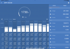
Why they even bother with 150v pvmax is beyond me, i hit that so fast with just 3 or 4 panels…. I ended up getting a victron mppt RS 450/200. It has 4 totally independent solar charge controllers (trackers) (I’m only using 2 at present, 1 for a small 4 panel string on the roof of the RV, the other for. Large 7 panel string on a building roof), I love it….
Attachments
Last edited:
dougbert
Solar Addict
I just stumbled across a local dealer for the Sigineer inverters
they carry:
12kw for $2,200
15kw for $2810
18kw for $4200
I called them and he will get back to me on:
1) does their product have the Tesla charging profile available on their Selection #9? I think due to jack they added that to their entire lineup a couple of years ago. Their ad line has:
if it does, it will work as my 3 pole transfer switch disconnects the grid's neutral when the inverter is selected
The next great thing is, I can do a Will Call pickup and save the shipping. They are located some 50 miles from home
They are a dealer supporting Sigineer and that would be good for future support
If all the answers to my question are GOOD, then the 12kw version would match my needs perfectly as
it is in the ball park price of the Growatt's price, and a 12kw
(also, I think the Growatt 12k transformer IS using a Sigineer transformer, just has different control board and different interface features)
sure I would not have the digital monitoring etc, but would be able to utilize the entire battery capacity down to 38.0v LVD
when LVD occurs they switch off inverting and begins Grid charging of battery and support for the loads until the
battery is charged to 50.5 volts.
50.5 volts would work for me - my solar CC's are set to charge to 49.52, and solar does the bulk of the charging.
The grid charging would only occur infrequently, and less often as I add battery modules
I view the grid AS A BACKUP power source.
this just MIGHT work out
Affordable Electric Vehicle Batteries & Components from Electric Car Parts Company
Electric Car Parts Company is your one-stop-shop for affordable electric vehicle parts and components including batteries. Shop our selection and order now!
www.electriccarpartscompany.com
they carry:
12kw for $2,200
15kw for $2810
18kw for $4200
I called them and he will get back to me on:
1) does their product have the Tesla charging profile available on their Selection #9? I think due to jack they added that to their entire lineup a couple of years ago. Their ad line has:
Works With Lithium or Lead Acid Batteries
2) does it have an internal N-G Bond switch? He gave me a verbal that it does have an ENABLE/DISABLE switch, but will follow up with an emailif it does, it will work as my 3 pole transfer switch disconnects the grid's neutral when the inverter is selected
The next great thing is, I can do a Will Call pickup and save the shipping. They are located some 50 miles from home
They are a dealer supporting Sigineer and that would be good for future support
If all the answers to my question are GOOD, then the 12kw version would match my needs perfectly as
it is in the ball park price of the Growatt's price, and a 12kw
(also, I think the Growatt 12k transformer IS using a Sigineer transformer, just has different control board and different interface features)
sure I would not have the digital monitoring etc, but would be able to utilize the entire battery capacity down to 38.0v LVD
when LVD occurs they switch off inverting and begins Grid charging of battery and support for the loads until the
battery is charged to 50.5 volts.
50.5 volts would work for me - my solar CC's are set to charge to 49.52, and solar does the bulk of the charging.
The grid charging would only occur infrequently, and less often as I add battery modules
I view the grid AS A BACKUP power source.
this just MIGHT work out
Last edited:
Similar threads
- Replies
- 4
- Views
- 327
- Replies
- 95
- Views
- 2K
- Replies
- 2
- Views
- 295
- Replies
- 24
- Views
- 1K


