Cant wait to see pics…with the new tesla module additions pending (1 here now, 1 shipped today), I am finally going to change the wiring of the modules
Instead of daisy chaining cables from module to module (or set of modules as you will see), I am finally going to install my 2"x14"x5' copper buss bars. Then remove battery cables and setup them up to connect to the buss bars.
You are using an out of date browser. It may not display this or other websites correctly.
You should upgrade or use an alternative browser.
You should upgrade or use an alternative browser.
Solar house generator I started DIY back in 2000 - My path from Trace to Xantrex (on FLA battery) to XW Pro inverters on Tesla Model S batteries
- Thread starter dougbert
- Start date
dougbert
Solar Addict
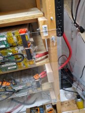
here is the POS side of the battery, with current 2 contact points:
1) bottom row of 2 layers of 2 modules. POS connector from the Battery controller is also attached here.
You can see the copper U bar connecting 2 layers of modules together. (Has the black heat shrink)
2) second row of 3 layers of 2 modules above that, this row with 2 U bars stack connecting the 3 layers
Also notice the 2x4 with a nut holding it to the vertical. That is this area that the POS buss bar will be attached with isolated offsets (see below)
and yes all the cables are 4/0 in size
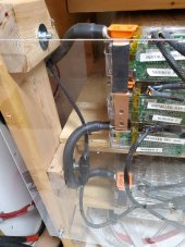
Here is the NEG side of the 2 row of 3 layers of modules. Top cable runs to the ESP32 BMC (nicked named "Jack-in-the-box" aka JITB by congressman Massie from Kentucky. He is a MIT engineering graduate who designed and implemented the display running on a raspiberry pie)
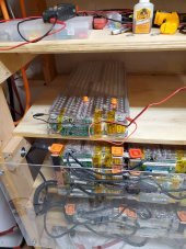
Module 11 waiting for Module 12 to arrive next week
being charged to 23.00 volts. The incoming module also be charged to 23.00 volts
that will result in 26.00 volts for the 2 of them in series
then I monitor and wait for the main pack to also reach 26.0 volts then insert the new modules into the pack
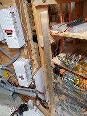
That vertical shiny thing is the 2"x1/4"x5' copper buss bar, near the NEG position
it will be setup with the offset insulators attached to the vertical 2x4
When the cables are attached, it will be covered in water pipe insulators, like pool noodles
Pipe Insulation - Plumbing - The Home Depot
Get free shipping on qualified Pipe Insulation products or Buy Online Pick Up in Store today in the Plumbing Department.
www.homedepot.com
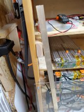
Another shot of the buss bar
I will drill a hole on top of the NEG side bar for the NEG JITB contact
Another hole on the bottom of the POS side bar for the POS JITB contact
Then more holes for each of the rows - maybe more later if needed
Here is the link to the INSULATOR. I bought 4 this morning
HARGER R4150A4 3/8X1-3/4X1-1/2 INSLTR | Gordon Electric Supply, Inc.
HARGER R4150A4 3/8-16X1-3/4X1-7/8 INSULATOR
for the 2 buss bars I ordered from www.onlinemetals.com
1/4" x 2" Copper Full Round Edge 110-H02 Silver Flash | Online Metals
View our full selection of 0.25" x 2" Copper Full Round Edge 110-H02 Silver Flash stock today on our website. Buy online with fast shipping direct to your door.
WOW I bought 1 bar in July 2020 for $108 including the shipping
looking at their link above today, the same bar is $295 + Shipping
I have 2 of them.
Last edited:
dougbert
Solar Addict
Right now when I add another pair of modules I need to disassemble the old contact points to adjust cables
moving to a buss bar, when adding a new row - like this next one - I will just need to add the cables from the bar to the modules
much easier and better as well
moving to a buss bar, when adding a new row - like this next one - I will just need to add the cables from the bar to the modules
much easier and better as well
dougbert
Solar Addict
When I installed my first 4000 watt inverter (Trace SW4024) back in 2000, I also purchased and installed their Balance Of System (BoS) components, which housed the 250a DC breaker, and charge controller breakers (of which I allowed for 3 - now I have 4). Those are the middle 2 boxes between the inverter on the left and MPPT #1 on the right. As I refactored for the Xantrex inverter I kept the older BoS parts and "adapted" things to fit.
Reusing these BoS boxes worked functionally, but proved difficult in wall space layout.
Since I didn't get the Schneider PDP and XW Pro then, I had to jerry rig breakers and the 4 Charge Controllers in order to get things working with the older BoS.
But with the new plan, I am going to remove ALL of the DC components as well as the Xantrex inverter, from the wall space (66" wide by 52" tall) to make space for the new XW Pro BoS parts and inverter
here is what it looks like now - brace your self for ugly:
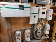
Yes, goes inn'a and goes out'a wires for the 4 CC's
When that is gone, I will rebuild with 1 Conext XW Pro inverter now (but allowing wall space for a future 2nd inverter to the left side) and the Conext PDP. I will place 2 of my current CC's alongside the PDP and the remaining 2 CC's 6 inches to the right of the first 2.
It will look like the following pic I found of someone else's install:
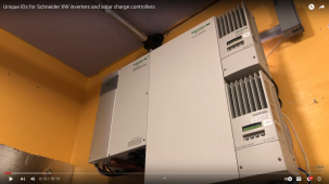
the empty space below the inverter on the left, will be covered with a Conduit box.
When/if I add a 2nd inverter it would be installed on the left of inverter number one.
most of the wires will be hidden in the PDP and the lower Conduit Box, etc
SOOO
it will clean things up A LOT
Reusing these BoS boxes worked functionally, but proved difficult in wall space layout.
Since I didn't get the Schneider PDP and XW Pro then, I had to jerry rig breakers and the 4 Charge Controllers in order to get things working with the older BoS.
But with the new plan, I am going to remove ALL of the DC components as well as the Xantrex inverter, from the wall space (66" wide by 52" tall) to make space for the new XW Pro BoS parts and inverter
here is what it looks like now - brace your self for ugly:

Yes, goes inn'a and goes out'a wires for the 4 CC's
When that is gone, I will rebuild with 1 Conext XW Pro inverter now (but allowing wall space for a future 2nd inverter to the left side) and the Conext PDP. I will place 2 of my current CC's alongside the PDP and the remaining 2 CC's 6 inches to the right of the first 2.
It will look like the following pic I found of someone else's install:

the empty space below the inverter on the left, will be covered with a Conduit box.
When/if I add a 2nd inverter it would be installed on the left of inverter number one.
most of the wires will be hidden in the PDP and the lower Conduit Box, etc
SOOO
it will clean things up A LOT
Last edited:
dougbert
Solar Addict
I learned some interesting points on the results testing the XW Pro vs Sol-Ark
Hedges
I See Electromagnetic Fields!
- Joined
- Mar 28, 2020
- Messages
- 20,522
It will look like the following pic I found of someone else's install:
"6 inches clearance above", the SCC manual says.
Looks like those are cooled by convection only, so leaving more space than "someone else" did should let them run cooler for longer life.
I try to always have a tee with unused leg, so conduit connections can be expanded by adding on. But your wiring box may provide for that.
dougbert
Solar Addict
It took a lot of searching to find a picture of an installed system, and here it a Xantrex one, so it is a few years ago. Yet the sizes are the same. I had a similiar question when I finally found the picture. I will recheck the fitment, it is THEIR design."6 inches clearance above", the SCC manual says.
Looks like those are cooled by convection only, so leaving more space than "someone else" did should let them run cooler for longer life.
I try to always have a tee with unused leg, so conduit connections can be expanded by adding on. But your wiring box may provide for that.
weird
Hedges
I See Electromagnetic Fields!
- Joined
- Mar 28, 2020
- Messages
- 20,522
Probably a case of left hand not knowing what the right hand is doing.
Thermal considerations would have gone into the clearance spec, considering hottest environment and highest power dissipation.
You will know better what Vmp/Imp your array feeds, and if you can find efficiency curves (which I don't see in their manual or specs) then you can estimate how much cooler yours would run.
You can also check heatsink temperature of your present system.
What made my Sunny Boys so hot was I installed them in the sun before RTFM.
Hedges
I See Electromagnetic Fields!
- Joined
- Mar 28, 2020
- Messages
- 20,522
??
You're lucky if the specs a company publishes are even what the engineers designed and tested.
Or was the "Wow" over my hot inverters?
SWR 2500U has no fan, just a large black heatsink on top. Its specs (which I do believe) allow quite hot operation. Will derate itself if necessary.
Instructions said to put in shade, but I hung on a South wall. When the sun was on it it got quite hot. I placed a Pabst fan on it with extra panel to power that. Also a plastic corrugated roof. Maybe heat shortened lifespan, but my failure rate worked out to about 35 year MTBF.
dougbert
Solar Addict
your hot inverters - lol on my part??
You're lucky if the specs a company publishes are even what the engineers designed and tested.
Or was the "Wow" over my hot inverters?
SWR 2500U has no fan, just a large black heatsink on top. Its specs (which I do believe) allow quite hot operation. Will derate itself if necessary.
Instructions said to put in shade, but I hung on a South wall. When the sun was on it it got quite hot. I placed a Pabst fan on it with extra panel to power that. Also a plastic corrugated roof. Maybe heat shortened lifespan, but my failure rate worked out to about 35 year MTBF.
dougbert
Solar Addict
Oh I see one possibility: the CC's are less deep than the PDP, and thus have a third "side' (the back side) with an air gap between themselves and the wall. Possible the engineers factored that 3rd side for more convection cooling. One can see the space in the picture
Hedges
I See Electromagnetic Fields!
- Joined
- Mar 28, 2020
- Messages
- 20,522
Position two like that, load them the same, measure heatsink temperatures. The ratio of temperature rise may hold for full load. Or not, gas flow is awfully complicated.
I have little faith in companies getting everything right. They tend to lose the tribal knowledge of earlier engineering staff.
I have little faith in companies getting everything right. They tend to lose the tribal knowledge of earlier engineering staff.
dougbert
Solar Addict
and I learned I can add a solution of my design: Add a 12vdc muffin fan below them both and blow upward. Making it active flow. meh. I got the power AND an existing control set of lines. in my pic, the gray panel on the upper left contains 4 contactors, one for each incoming array. that is turned on the ESP32 BMC when it is OK to charge. Turns off when it is NOT okay to charge.Position two like that, load them the same, measure heatsink temperatures. The ratio of temperature rise may hold for full load. Or not, gas flow is awfully complicated.
I have little faith in companies getting everything right. They tend to lose the tribal knowledge of earlier engineering staff.
It is not like I am going to get an exam by factory dudes on my installation.
thanks
dougbert
Solar Addict
When I installed/wired up my existing system with the Trace SW4024 a decade ago (the inverter prior to the Xantrex inverter), (120v) I didn't (meaning lazy) install 2 wires for L1 and L2. I only installed wire for L1
well yesterdayI pulled a wire for L2 from my original inside service panel upstairs in the back hall down to the basement where the solar system resides. Just had to pull to the breaker box above the transfer switch. Further down stream wires were already there. I had some difficulting get that wire pulled, but I had short segments of conduit. 3 segments and it worked, thus that leg in now installed all the way to the inverter input area (which the current inverter can't use) and from the inverter output area (which current inverter doesn't provide) to the main critical loads panel. therefore, the 240v feedin is in place for the future 240v inverter.
Next is to pull another wire, L2, from the main critical loads panel in the basement to the back hall to the sub critical loads panel which located beneath the grid main panel.
I sure wish I had known what I was going to do with solar back when I upgraded the house in 1995, Things would have been much better now.
ADVICE to others: put in big service panels even with small mains. And add levels of indirection - like 2 service panels next to each other for future expansion of solar between main service and entrance service
Lastly debating whether to run a L2 leg from the main critical loads panel out to the detached garage (not usable by a car - it is basically the storage shed). It has a small 120v panel out there. Much longer run and need more wire
Once I get the 240v system setup. I will able to run a 240v 50 amp circuit outside to the drive way for the future EV Stage 2 charging port. Right, dream on getting an EV in my life time
Last edited:
dougbert
Solar Addict
And I did order the XW Pro PDP box, getting ready to order the Pro itself - well in a few months. I have to build wire by wire and box by box
dougbert
Solar Addict
@Hedges, got some questions for you if you wouldn't mind and you might know the answers.
My experience with my system has been:
1) Early on used as an UPS, with solar assist
2) Then moved to totally running the house with active PV generation and battery storage. Using the grid to ONLY run loads via by-pass while the PV CC's charged the battery to a specified level, then drop grid - did not charge all the way up. Rather about 1/3 full then drop grid
I used the GRID as BACKUP to the batteries, not as primary source. Effectively, I ran Off GRID and rarely needed the GRID to back me up. When the battery reached LBCO, Low Battery Cut Out, the inverter would switch to Grid running loads.
Now I am reading how to program the XW Pro for similar operation, and as a hybrid, it definitely has a different operating model. It looks like most who have grid, use netmetering - well yeah - do not cycle the batteries much. That is different than what I have done.
I do not do netmetering, for 2 reasons:
1) I don't want utility/gov in my power production/consumption business - Selfish Solar: I produce here, I store it here and I use it here\
2) My city power utility serves some 20,000 people here in Utah, rural valley. It has several "circuits", each serves portions of the area. My circuit where my house sits, is currently FULL and they will not accept any more Netmetering customers until .... well some time in the future
As I explain in the following, please understand I do NOT fully know about Load Shaving, Peak Load Shaving, and Grid Support operations provided by the XW Pro, even I as I am re-reading the documentation several times. Thus I need to research and understand the model and operations these features run on first.
I did find TOU Metering feature, which I have used 15 years ago on my old Trace.
I am seeking for the best way to configure the XW Pro to provide my Off Grid mode of operation, using the Grid only for battery backup
Would appreciate a general direction to look at to do this.
Last edited:
Hedges
I See Electromagnetic Fields!
- Joined
- Mar 28, 2020
- Messages
- 20,522
I've never used the XW, would just have to start by reading manual. Some others here have Trace/Schneider products. @GXMnow in particular has also used Raspberry Pi or similar to command behaviors (related I think to coupling with Enphase microinverters.)
Some inverters allow current transformers on the wires coming from grid, so they can backfeed into the house but avoid backfeeding the grid. "Zero Export". That seems like the best way, if you don't have whole house downstream of inverter.
With my Sunny Island I know I can program to run battery down, connect to grid for charging if needed. But given limited cycles of AGM and cost per cycle, I don't do that, just keep it floating. SI doesn't seem to have all the export control functions I would want. Sunny Boy Storage I think has that. Could be the European model SI does, not available here yet.
Obviously you want to control loads to fully utilize PV generation. Having batteries able to buffer the power by cycling could make that feasible with variable loads.
dougbert
Solar Addict
I have read or am reading the following threads, and have gleaned some info so far in learning what to do for my up coming XW Pro arrival.
https://diysolarforum.com/threads/adding-storage-to-my-enphase-system.10797/ 56 pages, @GXMnow
https://diysolarforum.com/threads/adding-schneider-xw-pro.19090/ 26 pages, way to go @400bird
https://diysolarforum.com/threads/schneider-conext-xw.11037/ 8 pages, again 400bird
Points:
I am not netmetering/not selling power back to the grid AND since I am DC coupled and am charging my battery from the DC controllers, I do not really need the inverter/charger to charge my battery. Rather, just use the inverter operation only
I can still set it up with the proper charging profile - the same as in the DC charge controller, in case I might need to grid charge. DO that manually and not automatically. Voltage range is 37 to 50.4. I bulk/absorb/float to 49.5, leaving head room on top. Cell voltage range is 3.0 to 4.2
Allow battery to drop to 38vdc for LBCO. When that is crossed, the grid will kick in AC bypass mode, allowing the DC chargers to charge the battery back up. House will live on grid until the voltage is reached set in the DC chargers
Last major LBCO event was last december several times. that month I did around 51% solar, 49% grid. Since January, it has been 98% or so total solar generation
looking at other settings
Last edited:
400bird
Solar Wizard
Oh my, I don't know that I've ever been summoned before. Thanks for the encouragement!
Looks like your having lots of fun. Was there a question I can assist with? I'm not sure I saw a question.
Do you want the battery/XW to support any loads in the main panel? Otherwise it does a great job of supporting loads on the output/back up panel.
There's about 4,000 settings. It's a bit overwhelming and the timers all function backwards. "When do you not want to do this function?"
But, that's probably a carry over from the Trace/Xantrex days so you're well familiar.
dougbert
Solar Addict
summoned? oh I guess I did, lolOh my, I don't know that I've ever been summoned before. Thanks for the encouragement!
Looks like your having lots of fun. Was there a question I can assist with? I'm not sure I saw a question.
Do you want the battery/XW to support any loads in the main panel? Otherwise it does a great job of supporting loads on the output/back up panel.
There's about 4,000 settings. It's a bit overwhelming and the timers all function backwards. "When do you not want to do this function?"
But, that's probably a carry over from the Trace/Xantrex days so you're well familiar.
yes, you have some good threads
well, in my post 518 https://diysolarforum.com/threads/s...-2000-on-my-house-and-it-shows.11/post-602904
I have a basic foundation of my build along with requests, and now with the up coming XW Pro I am wondering general direction of which settings should I look at?
thanks
Last edited:
Similar threads
- Replies
- 4
- Views
- 327
- Replies
- 95
- Views
- 2K
- Replies
- 2
- Views
- 295
- Replies
- 24
- Views
- 1K


