diy solar

diy solar

How to connect EVE dual thread terminal cells in two rows?

Metricsys

New Member
Joined
Sep 7, 2022
Messages
12
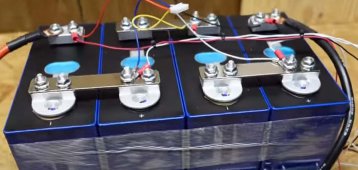
I was wondering how to connect the new EVE dual thread terminal cells when they are in two rows? not wide side wall to wide side wall but end wall next to end wall position. I only saw bus bars that designed for one row connection. Should I us two bus bars?
 
Last edited:
What’s the distance you are measuring between threads when short end to short end? It’s probably a standard size.
 
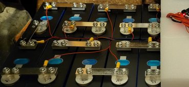
I just used the same bus bar, on one stud each. With all other cells, you only get one stud. I figure that I can live with it for one connection. You could double up, but I don't think it's necessary.
 
Temp is the same, throughout all connections.
As I said, any other cells only have one stud. Having two is definitely better. But, one is all that is needed.
 
I like the through bolt design. Can crank on it without worry of cell damage..
It's a great design. Even if you managed to strip it out, it would be easy to re tap it to a larger thread. These are the only cells I will be purchasing from now on. (Unless something better comes along)
 
It's a great design. Even if you managed to strip it out, it would be easy to re tap it to a larger thread. These are the only cells I will be purchasing from now on. (Unless something better comes along)
Honestly I didn’t even know they were tapped.
Just figured you through bolted with flange nut and use the surface area of the lug to Busbars as contact area. Neat Design.
 
If you clean battery aluminum terminal surface to remove aluminum oxide build up, the measurements stated below were made with normal single post EVA cells with raw aluminum terminal flats.

These double post terminals need to be checked to see if they are a 'COALR-like' plated surface and not just bare aluminum. Their dull appearance makes me think they are cad plated, like electrical panel box connection terminals compatible with aluminum or copper wire. This would give their surface a slightly higher resistance than clean bare aluminum but would not suffer aluminum oxide build up, giving them a more user-friendly consistent surface to surface contact resistance without significant cleaning.

Based on a quantity of about 75 single post EVA cell bare aluminum terminal connection with high current four point resistance measurements, the basis series resistance for a good clean nickel plated bus bar average was:

- Single post/nut only component of cell terminal flat to bus bar surface series resistance = 0.05 milliohm on average. If surface of a bare aluminum battery terminal flat is not cleaned of aluminum oxide first, the resistance is highly variable and can easily be upwards of over 0.15 milliohm each.

- A nickel plated copper core bus bar of 2 mm thickness, 20 mm width, and 72 mm hole to hole spacing has a series resistance of 0.04 milliohms on average.

If you have a cheap brass core bus bar, their bus bar only piece of series resistance for same dimensions is 0.17 milliohms on average compared to 0.04 milliohm for nickel plated copper core bus bar.

For an old bare aluminum terminal EVA cell with single post, the two-cell terminal-to-terminal connection resistance is 0.05 mohm + 0.04 mohm + 0.05 mohm = 0.14 milliohm on average for copper core bus bars. That is about 7 mV drop between cell terminals for 50 amp inverter current.

With double posts, you can assume the net terminal post to bus bar surface contact resistance would drop by about half from 0.05 milliohm to 0.025 milliohm.

That would yield 0.025 + 0.04 + 0.025 = 0.09 milliohm cell terminal to cell terminal series resistance. About 5 mV drop between cell terminals at 50 amp inverter current. Again, this may be slightly higher if the double post has a COALR-like plated surface.
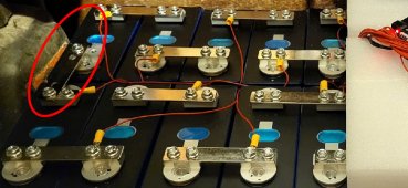
double post bus bar.jpg

Issue comes in on the picture's middle left side bus bar connection. It has a slightly longer distance than 72 mm's, it lacks the double post connections, and more importantly, there are two empty holes drilled in bus bar between connections that will significantly increase bus bar resistance. At 50 amps of inverter current, I would expect about 15-18 mV drop between these two battery terminals versus about 4-6 mV drop across other double post bus bars. The minimum thing to do is get a regular single hole pair bus bar to replace the four holed bus bar. That would get 50-amp voltage drop to about 8-12 mV, not great, but better.

For moderate inverter load current, the picture's middle left side bus bar connection will cause higher cell voltage reading on BMS for the upper right hand corner cell due to the extra resistance in that particular bus bar's voltage sense wire connection points. This can screw up BMS balancing when there is variable amount of charging current or inverter discharge current when balancing voltage sensing is happening.
 
While I can appreciate the information. I personally don't think that a battery for a home solar system needs to be held to such high standards. If it were going in a space ship or race car, it might make a difference. I don't think that a few mv difference would affect the performance or life expectancy in this use case. My cells balance perfectly and that connection sees no increase in heat from the others. So, calendar aging should still be the only degrading factor.
In my honest opinion.
 
It's a great design. Even if you managed to strip it out, it would be easy to re tap it to a larger thread. These are the only cells I will be purchasing from now on. (Unless something better comes along)
I think the weakness is the weld of the double threaded adapter to the cell. Been a few reports of the adapter being bent due to packaging issues. Also any weld can fail, not saying there’s been issues with the welds but is prob the only weak link.

Also I believe there are threaded inserts (helicoli) if you strip one of those out something else was driving factor.
Yeah, it would be very hard to strip out. They are pretty thick. It would take some extra ordinary force.
So far, I think that they are the best version available.
I believe in them enough to purchase 124 of them. lol
 
Somewhere someone suggested the possibility of installing a nut underneath the terminal into which a bolt could be screwed thereby allowing much greater clamping forces. However, on my cells, the space underneath the terminal is only approximately 2mm thick. I am not aware of any nuts that thin. Besides, a 2mm thick nut would likely be too thin for practical use.
 
Again check see if there is a helicoil for each threaded connection, if so you have nothing to worry about when tightening down to 5-10nm per the spec. Anything above that isn’t solving a bad electrical connection.
 
Somewhere someone suggested the possibility of installing a nut underneath the terminal into which a bolt could be screwed thereby allowing much greater clamping forces. However, on my cells, the space underneath the terminal is only approximately 2mm thick. I am not aware of any nuts that thin. Besides, a 2mm thick nut would likely be too thin for practical use.
Not much space between the cell and the bottom of the terminal. I suppose you could mill out some metal?
 
There's more than enough thread. No need for a nut.
I think you are trying to fix a problem that doesn't exist.
 
Back
Top