diy solar

diy solar

Where does the load go on this DC circuit breaker?

meetyg

Solar Enthusiast
Joined
Jun 4, 2021
Messages
1,089
Hi.
I recently got this type of DC circuit breaker:
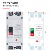
TXCM1B-Moulded-Case-Circuit-Breaker-Battery-Battery-DC12V-24V-48V-Car-Charging-Pile-Protector-...jpg
It's a 2 pole DC breaker, mine is rated for 160ADC, but has same connection drawing as in the picture.
I will use it to connect my 24v Lifepo4 battery to my 3k 24v inverter.

My question is, where does the load (inverter) go, and where does the battery?

From my understanding of the little schematic, the load goes on the bottom, but I'm not totally sure.

The inverter is an AIO, so it will also charge the battery, but I suppose that most of the current will be the inverter pulling from the battery.

Your help is appreciated!
 
Unfortunately your circuit breaker is polarized; so is uni-directional only.
Source power (battery) + top LHS, - top RHS
Load + bottom LHS, - Bottom RHS

As it isn't bi-directional, is unsuitable for use when the load side can also push charge back into the battery.
You can purchase these types of breakers that are not polarized; and that is what I would get for your suggested application.

Cheers
Mike
 
Darn it...
I thought that polarized meant that you have to connect positive to positive and negative to negative, not switching them. Didn't know that it mean only one direction protection.

These things aren't cheap either. Cost me around $65.

Is it dangerous to use them when inverter will charge the battery ? Because if it's not dangerous, then for added protection when charging I could just add a fuse on the battery.
 
>> Is it dangerous to use them when inverter will charge the battery ? Because if it's not dangerous, then for added protection when charging I could just add a fuse on the battery.

Well you could go ahead and use it, mount it close to the battery; Its unlikely the inverter in charge mode will overload the breaker, remember the breaker is there to protect the battery and supply cables if there is a short in your inverter (load) and also provide isolation if required. The inverter charger cct should have its own charging fuse within it somewhere.

If you add extra external PV chargers to the battery, wire them each with a separate breaker or fuse direct to the battery terminals, not to that existing breaker.

3Kw for an extended period at 80% inverter efficiency may trip that breaker.

Cheers
Mike
 
If memory serves all un-grounded conductors require over-current protection.
I'm not sure if that means grounded conductors must not have over-current protection.
Etiher way, if the system is intentially floating I don't see the harm in a double-pole breaker.
 
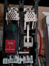
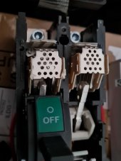
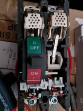
Can you tell from this if the DC breaker is polarized? This is the TAIXI MCCB that I got.
The seller on Aliexpress says that it's not...
20220925_104003.jpg20220925_104022.jpg20220925_104024.jpg

Seems like both poles have the arc chamber.
When checking continuity on the terminals, each pole is disconnected from the other.
 
Their images of the dual pole device clearly show polarizing +- symbols, they also say it can be used for AC at a higher voltage.
Looks like its actually an AC mccb with no magnets for arc diversion, with a voltage derating usage at DC.

I guess you are taking a risk using it as it seems not designed for DC only.
 
Who knows, I have sent them an email asking the question, polarized or not for the single pole breaker; will report back when I get a reply.
 
I should not wade into this.

Asking if a DC breaker is polarized when you really want to know if it is Bi-directional will give you the wrong answer.

By convention most all breakers are built directional with the supply coming into the top and the load going from the bottom. The switch lever points to the supply when on. In practice AC breakers do not really care which is supply and load however DC breakers do. All DC breakers are one direction (regardless of the terminal you wire (+) or (-) to.) Polarized simply means that it matters if the terminal is wired for (+) or (-) and not which direction supply and load is wired.

Unless a DC breaker is labeled as Bi-directional it is not.

Why does this matter? Up until the AIO's you did not back feed your battery from the same conductors you supplied the inverter with. You could put a directional DC breaker going from the SCC output to the battery and another DC breaker from the battery to the inverter.

So if you want to protect your circuit in a AIO going to and from the battery use a fuse. The breaker (I like it wired so that the battery is considered the supply since most likely the largest current flow will be from it since charge current is most likely less than discharge) can be used as a disconnect.
 
I have received reply back from seller, that single pole breaker is NON-Polarized, can go in + or- lead.

Guess that makes it bi-directional, so can be used for battery connection with both charge and discharge circuits.....
 
Your guess is incorrect. If it is not rated and labeled as Bi-directional DC it is not Bi-directional. However feel free to wire the (+) lug with the negative wire and the (-) lug with the positive wire so long as you do it the same top and bottom and supply to load.

I knew I did not want to comment.
 
Unless a DC breaker is labeled as Bi-directional it is not.

Why does this matter? Up until the AIO's you did not back feed your battery from the same conductors you supplied the inverter with. You could put a directional DC breaker going from the SCC output to the battery and another DC breaker from the battery to the inverter.
What am I missing?

My 23 year old Trace inverters charge the batteries on the same wires going through the same breaker. Is that what you're referring to?

Trace which turned into Schneider and Outback have used this style of DC breaker in DC load centers for at least 25 years. No mention of polarity or directional that I see. Can I just keep using these?
The breaker you list is not rated as Bi-directional. DC load centers are designed with a supply side and load side. Small amounts of current backflow in a DC breaker has not been much problem but with the advent of these high voltage/current AIO's there is now a problem with backfeed current interruption. Certainly you can keep using your present setup but it should be fused for bidirectional protection.

Unfortunately some people in the solar world has created a false description they called polarized (which any electrician who wires for correct polarity should have tossed the Red flag at) to try say that a DC breaker that is non polarized is Bi-directional. A simple Google search for Bidirectional DC breakers would answer the query but instead the mythology continues.

ETA: It just occurred to me that using two DC breakers wired such as they were opposite direction would provide protection in both directions. Not sure if it has been tested out.
 
Last edited:
Hi.
I recently got this type of DC circuit breaker:
View attachment 112781
It's a 2 pole DC breaker, mine is rated for 160ADC, but has same connection drawing as in the picture.
I will use it to connect my 24v Lifepo4 battery to my 3k 24v inverter.

My question is, where does the load (inverter) go, and where does the battery?

From my understanding of the little schematic, the load goes on the bottom, but I'm not totally sure.

The inverter is an AIO, so it will also charge the battery, but I suppose that most of the current will be the inverter pulling from the battery.

Your help is appreciated!
Top is the source. Left side top terminal is '+' meaning it is the most positive. This is PV panel positive lead. The right side top is '-' is the most negative voltage. It is the negative side and is the PV panel negative terminal. (see the label diagram to right of switch )

Terminals directly below at bottom of breaker go to charge controller inputs, left is pos, right is neg.

Breaker should be oriented as shown in picture. Not mounted on side or upside down. Many HV DC breaker partially rely on hot plasma arc that happens when you open breaker to flare upward to assist breaker's arc suppressors to quench the arc as quickly as possible.

For most PV GT inverters and HF hybrid AIO inverters the PV lines are not isolated from AC so they need both PV panel pos and neg terminal switched, therefore the reason for double pole breaker. The pos and neg PV lines from AIO charge controller will be riding on top of a high voltage square wave at the frequency of AC. Never allow either of the AIO charge controller PV inputs wires to accidentally touch neutral/ground on a HF hybrid inverter when it is active producing AC output, or you may damage inverter. Best to have inverter powered down when working on PV wiring connections.
 
Last edited:
...

Breaker should be oriented as shown in picture. Not mounted on side or upside down. Many HV DC breaker partially rely on hot plasma arc that happens when you open breaker to flare upward to assist breaker's arc suppressors to quench the arc as quickly as possible.

...
Interesting. I was unaware that orientation of breaker mounting was a concern. Thanks for explaining it. (y)
 
This is what a PV HV array breaker is being subjected to when opening breaker. (500vdc array shown).

A HV DC breaker has a metal grid fin array to suppress arc, many have magnets to push arc current in a desired direction, and many rely on orientation so rising arc is pushed into metal grid fin suppressor. Besides orientation, polarity matters when there are magnets to direct arc direction.

PV arc 600v array.jpg
 
Last edited:
Small amounts of current backflow in a DC breaker has not been much problem but with the advent of these high voltage/current AIO's there is now a problem with backfeed current interruption. Certainly you can keep using your present setup but it should be fused for bidirectional protection.
This is helping. Thanks. I've Googled this topic several times and it only reveals scientific papers that are well above my head.

Can you define "small amount"? Between my solar (~100 a) and the inverter chargers (~130a) I can get to ~230 amps charging at 48v nominal total for the system. In practice that rarely happens and it's split between two breakers. Ahh!! Now that I think about it the wire that feeds DC Buss that the PV is hooked up to (and DC loads if I had them) is from the battery side of one inverter breaker so that means that only 130 amps from the inverter chargers is coming from the inverters and that is actually split between each inverter's breakers so each one of those breaker is seeing 65 amps of current. Still 65 amps is would not be small in my tiny mind.

I I always put a Class T fuse as close to the battery as possible.
 
Back
Top