diy solar

diy solar

Small Boat BMS/LFP with backup

Great. I can show that improvement next.

I think I should change the label to "LFP Bypass Override - Used for LVD to enable charging."

I had an idea. When the BMS/LFP disconnects is there a way to get it to automatically shift to SLA Emergency so navigation and lights are not interrupted and no manual operation is needed? Or is that too complicated?
Getting a bit complicated for an event that should never happen. Your Cerbo should be screaming at you long before LVE disconnect.
 
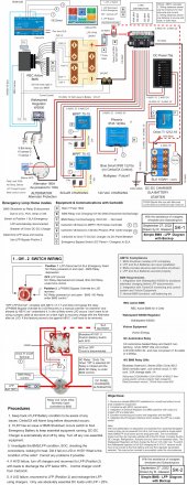
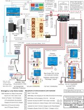
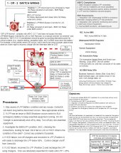
Revisions are, improvement to 1-Off-2 Switch, automatic on/off of Orion Tr depending on Switch position, clarifications regarding ABYC and labeling.

Simple BMS -LFP Rev 9-27-2022.jpg
 

Attachments

  • Simple BMS -LFP Rev 9-27-2022.pdf
    6.9 MB · Views: 7
  • Simple BMS -LFP Rev 9-27-2022.zip
    3.8 MB · Views: 7
We need a fuse on starter battery to Orion-Tr.
Also move the inline 15a fuses on MPPT up to just before the Lynx
Also need solar DC breakers can be on a DIN rail with surge suppressors, all that goes on the negative from the solar panels
 
We need a fuse on starter battery to Orion-Tr.
Also move the inline 15a fuses on MPPT up to just before the Lynx
Also need solar DC breakers can be on a DIN rail with surge suppressors, all that goes on the negative from the solar panels
Can never see the point of dc breakers on the solar
 
Can never see the point of dc breakers on the solar
It makes sense for large current, high voltage arrays... for what we can fit on a small boat? Yeah, just disconnecting the MC4s is adequate. I'm using 24V panels, so my Voc is 36V or so, which is safe to handle. It would be different if I was running 72Voc or higher.
 
Thanks. @svsagres @Goboatingnow

Yes, I've been disconnecting the the MC4's before hurricanes, with our new dodger SunPower panels. Its only 100w right now.
Two SunPower 50w + Two Sungard Controllers

Photos of installation:

They are easily stowed before tropical storms and hurricanes, at some point before installing lithium I will change to MPPT controllers that are mounted inside where it is dry!

However don't I need to have some 5a fuses in the Solar Panel circuits?

LATER: When to fuse a Solar Panel Array.
Model SPR-E-Flex-50​
Nominal Power (Pnom) 50 W​
Power Tolerance +/–3%​
Rated Voltage (Vmpp) 18 V​
Rated Current (Impp) 2.8 A​
Open-circuit voltage (Voc) 21.5 V​
Short-circuit current (Isc) 3.0 A​
Power Temp Coefficient –0.35%/° C​
Voltage Temp Coefficient –58.9 mV/° C​
Current Temp Coefficient 2.6 mA/° C​
Max. System Voltage 45 V​
Series Fuse Rating 15 A​
LATER: Goboatingnow statement: https://www.cruisersforum.com/forum...i-reference-diagram-268921-2.html#post3685204

Also I think I will use the Lynx bus differently now. The MPPT wiring to the Lynx will be a dual set of wires up to the center +/- posts that don't support a fuse. I will then provide two inline 15a fuses just below the Lynx. I think this is more acceptable wiring.

The Orion Tr Charger can then be moved to the free fused +/- on the Lynx since we now have it automatically turned on when the Switch Position is in Off - LFP Normal. I still need to show a fuse at the battery.

Question: Isn't the RBS switch the same function as the "LFP Override" in the 1-Off-2 Switch above?

From the link above:
Keep in mind that any component can fail. I see the argument that when the BMS fails, the non-latching solenoid will open, protecting the battery. This argument is brought like if it is an advantage. Now imagine a battery that is 100% okay and the BMS fails, taking this good battery offline preventing you from hauling anchor during a violent squall that threatens to throw you on the rocks. The supposedly safety mechanism has turned into a disaster.

With the RBS, you can manually switch it off.

Likewise, instead of the BMS failing, the solenoid can fail. Imagine a massive power draw from the inverter and the BMS detects low voltage in cells and triggers LVC, but the solenoid contacts fuse together as they try to interrupt the large current.

For MOSFET based BMS’s it’s the same because MOSFETs normally fail in a shorted state.

Dealing with failing technology is a thing to consider. I like the RBS because it allows manual operation, even a lockout function, as well as remote switch and remote control by microcontroller. I also like the switch indicator signal that allows the microcontroller to learn the switch state. You can write a software routine that closes or opens the switch intelligently, instead of just sending a signal and pray it works.

What Jedi (Nick) says "With the RBS, you can manually switch it off." What he means is actually "Override the BMS". According to him this is in violation of

13.7.7 No electrical connections should be made directly to a lithium ion battery that would bypass a BMS or the protection relays.
 
Last edited:
It makes sense for large current, high voltage arrays... for what we can fit on a small boat? Yeah, just disconnecting the MC4s is adequate. I'm using 24V panels, so my Voc is 36V or so, which is safe to handle. It would be different if I was running 72Voc or higher.
It makes no sense to use fuses. The wire must be sized for Isc. The fuse must be at least Isc. There are no conditions when the fuse will ever blow.
 
Thanks. @svsagres @Goboatingnow

Yes, I've been disconnecting the the MC4's before hurricanes, with our new dodger SunPower panels. Its only 100w right now.
Two SunPower 50w + Two Sungard Controllers

Photos of installation:

They are easily stowed before tropical storms and hurricanes, at some point before installing lithium I will change to MPPT controllers that are mounted inside where it is dry!

However don't I need to have some 5a fuses in the Solar Panel circuits?

Also I think I will use the Lynx bus differently now. The MPPT wiring to the Lynx will be a dual set of wires up to the center +/- posts that don't support a fuse. I will then provide two inline 15a fuses just below the Lynx. I think this is more acceptable wiring.

The Orion Tr Charger can then be moved to the free fused +/- on the Lynx since we now have it automatically turned on when the Switch Position is in Off - LFP Normal. I still need to show a fuse at the battery.

Question: Isn't the RBS switch the same function as the "LFP Override" in the 1-Off-2 Switch above?

From the link above:


What Jedi (Nick) says "With the RBS, you can manually switch it off." What he means is actually "Override the BMS". According to him this is in violation of
Nick only ever listens to himself. !!!

13.5.3 Consideration should be given to providing alternative power for critical systems (e.g., engine starting,
navigation lights, etc) if a BMS shuts down the battery.

I would argue this gives grounds for a manual override
 
Thanks. @svsagres @Goboatingnow

Yes, I've been disconnecting the the MC4's before hurricanes, with our new dodger SunPower panels. Its only 100w right now.
Two SunPower 50w + Two Sungard Controllers

Photos of installation:

They are easily stowed before tropical storms and hurricanes, at some point before installing lithium I will change to MPPT controllers that are mounted inside where it is dry!

However don't I need to have some 5a fuses in the Solar Panel circuits?

No. The wiring is sized for Isc
Also I think I will use the Lynx bus differently now. The MPPT wiring to the Lynx will be a dual set of wires up to the center +/- posts that don't support a fuse. I will then provide two inline 15a fuses just below the Lynx. I think this is more acceptable wiring.

The Orion Tr Charger can then be moved to the free fused +/- on the Lynx since we now have it automatically turned on when the Switch Position is in Off - LFP Normal. I still need to show a fuse at the battery.

Question: Isn't the RBS switch the same function as the "LFP Override" in the 1-Off-2 Switch above?
No stop second guessing yourself Nick tends to only beleive his is the correct viewpoint

The RBS has a manual override but it has no way to go connect in the SLA. So now you need another switch ( like you had before ) now you again have the issue of protecting the SLA from inadvertent paralleling because the rbs relay could fail latched on
From the link above:


What Jedi (Nick) says "With the RBS, you can manually switch it off." What he means is actually "Override the BMS". According to him this is in violation of
Yes he’s contradicting himself
 
Note however you do it

The output of the mppt must be fused of that output is going to a battery. Ideally it should be fused both ends To protect against the wire touching something. But at least one fuse should be in the mppt output circuit.

I don’t see your justification in changing the wiring
 
Also I think I will use the Lynx bus differently now. The MPPT wiring to the Lynx will be a dual set of wires up to the center +/- posts that don't support a fuse. I will then provide two inline 15a fuses just below the Lynx. I think this is more acceptable wiring.

The Orion Tr Charger can then be moved to the free fused +/- on the Lynx since we now have it automatically turned on when the Switch Position is in Off - LFP Normal. I still need to show a fuse at the battery.

I don’t follow what you are doing here the original diagram is fine. You want the panels connected to the SLA cause this might be all you have.
 
I understand now that fuses on the solar panel side are not needed, since the panel wiring is #10 and
Now (2) on Dodger
Power 50w
Vmp 17.5v voltage
Imp 2.8a current
Voc 21.5v open circuit
Imc 2.95a short circuit current
Maximum series fuse 15a

Future (2) on Bimini/backstay or tracking stern poles.
Power 100w
Vmp 17.5v voltage
Imp 5.8a current
Voc 21.5v open circuit
Imc 6.2a short circuit current
Maximum series fuse 15a

Sorry, you don't follow, sometimes I don't describe things clearly, perhaps a diagram will help and if it isn't right, we'll just ignore the change.
 
I understand now that fuses on the solar panel side are not needed, since the panel wiring is #10 and


Sorry, you don't follow, sometimes I don't describe things clearly, perhaps a diagram will help and if it isn't right, we'll just ignore the change.
Correct re PV fusing. The mppt need at least one fuse on their output battery feed
 
Regarding moving the Orion Tr feed back to the Lynx bus. The reason it was moved to the DC Panel is svsagres felt it was not a supply into the LFP
see this post

Actually, the one other thing I would do is move the input to your Orion-TR to your DC panel, so that it's just another load device. it's not a supply into the battery, so shouldn't be on the supply side of things. You can also put it on a breaker or fuse off of your DC load panel, so you can turn it on/off as you see fit.

Yes, it is just another load device, agreed, and it does work nicely on the panel with a switch to turn it off if SLA is fully charged.
Also we have made it automatically turned off with the small 1-Off-2 relay, when in SLA Emergency mode. So I guess I will just leave it as it exists. We will use a small amp breaker in the panel for on-off, since we don't need an 18a breaker.
 
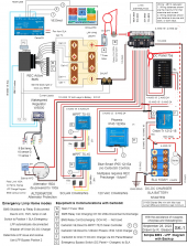
Here is the 9/28/2022 revision which adds a missing fuse, adds the Orion Tr DC panel switch at the 1-Off-2 switch, clarifies an ABYC question, and cleans up some notations.

SK-1 Diagram


Simple BMS -LFP Rev 9-28-2022-SK-1.jpg

SK-2 Switch, Objectives and Procedures

Simple BMS -LFP Rev 9-28-2022-SK-2.jpg
 

Attachments

  • Simple BMS -LFP Rev 9-28-2022-optimized.pdf
    4.3 MB · Views: 5
  • Simple BMS -LFP Rev 9-28-2022.zip
    3.9 MB · Views: 4
I have not read the whole post and this is based off the latest diagram. In Limp Home mode, all your LFP charging sources are connected directly to your SLA bank. Orion should be hooked up to Lynx to continue charging SLA via Alt, Solar or Phoenix. SLA should be then be switched in to DC panel and disconnected from Lynx.
 
AnarchyJet, I have not fully comprehended what I think is your somewhat complicated suggestion, but I believe we have discussed and addressed the Orion Tr operation, by automatically disconnecting it when on Pos 1 or 2 via the small NO Relay shown at the Switch so that we don't have a run-around circuit that may cause the regulator to just shut down.

BTW we have discussed that while the Orion is a charger, it is basically a consumer load and is most appropriately located on the DC Panel!
 
Last edited:
What happens when a 12.5v SLA is hooked up to that alternator, isn't it going to try and jam 100A into the battery? All the logic of disconnecting the BMS solenoid and 12->12 charger relay can be avoided with a 1-2-off switch
Sorry for butchering your nicely drawn layout. The red circles are 1-2-off switches. From LFP you can select between feeding the BMS solenoid, by passing it or isolate the battery.
Switch 2 selects if the DC panel is feed by Lynx, SLA or OFF
Orion is feed by Lynx, a switch could be inline if to turn it off.
This would eliminate all the relays, switches controlling the BMS solenoid and keep the SLA from being over charged.
1664401726271.png
 
Back
Top