You are using an out of date browser. It may not display this or other websites correctly.
You should upgrade or use an alternative browser.
You should upgrade or use an alternative browser.
Solar house generator I started DIY back in 2000 - My path from Trace to Xantrex (on FLA battery) to XW Pro inverters on Tesla Model S batteries
- Thread starter dougbert
- Start date
dougbert
Solar Addict
sorry I do notAnybody here have the Modbus Map aka table for the older ComBox fro Schneider ?
I am a SW dude, but have never programmed on ModBus
So where/how is the best place to learn the programming model, etc for accessing ModBus?
With XW Pro soon to be ordered and anexisting Gateway I am part of the way there
python preferred
I got python talking thru modbus to xw pro with gateway
works with insight too
its just wanting to hold onto a ComBox path to an older xw4548
I have never gotten the xw pro to work right with generator assisting. So i use the xw4548 from ac2 to charge my batt bank
write if you want more
works with insight too
its just wanting to hold onto a ComBox path to an older xw4548
I have never gotten the xw pro to work right with generator assisting. So i use the xw4548 from ac2 to charge my batt bank
write if you want more
dougbert
Solar Addict
any specific python libs?I got python talking thru modbus to xw pro with gateway
works with insight too
its just wanting to hold onto a ComBox path to an older xw4548
I have never gotten the xw pro to work right with generator assisting. So i use the xw4548 from ac2 to charge my batt bank
write if you want more
solar[3] = solarDev = ov_modbus.session('192.168.1.91',pollinterval=3,unit_id=1) # port=502 GATEWAY
solarDev.num = solarnum
sensor = ov_modbus.sensor(solarDev, 40278, 1, signed=False, divisor=100) # 40278 DC Bus Voltage
sensors['XW_DC_E'] = sensor
the above works on gateway but the below does not work with ComBox
solar[2] = solarDev = ov_modbus.session('192.168.1.92',pollinterval=3,unit_id=1) # port=502 COMBOX
solarDev.num = solarnum
sensor = ov_modbus.sensor(solarDev, 40278, 1, signed=False, divisor=100) # 40278 DC Bus Voltage
sensors['XW4548_DC_E'] = sensor
solarDev.num = solarnum
sensor = ov_modbus.sensor(solarDev, 40278, 1, signed=False, divisor=100) # 40278 DC Bus Voltage
sensors['XW_DC_E'] = sensor
the above works on gateway but the below does not work with ComBox
solar[2] = solarDev = ov_modbus.session('192.168.1.92',pollinterval=3,unit_id=1) # port=502 COMBOX
solarDev.num = solarnum
sensor = ov_modbus.sensor(solarDev, 40278, 1, signed=False, divisor=100) # 40278 DC Bus Voltage
sensors['XW4548_DC_E'] = sensor
dougbert
Solar Addict
solar[3] = solarDev = ov_modbus.session('192.168.1.91',pollinterval=3,unit_id=1) # port=502 GATEWAY
solarDev.num = solarnum
sensor = ov_modbus.sensor(solarDev, 40278, 1, signed=False, divisor=100) # 40278 DC Bus Voltage
sensors['XW_DC_E'] = sensor
the above works on gateway but the below does not work with ComBox
solar[2] = solarDev = ov_modbus.session('192.168.1.92',pollinterval=3,unit_id=1) # port=502 COMBOX
solarDev.num = solarnum
sensor = ov_modbus.sensor(solarDev, 40278, 1, signed=False, divisor=100) # 40278 DC Bus Voltage
sensors['XW4548_DC_E'] = sensor
I also saw you posted:
I think that happened
my geek son makes the ov_modbus stuff for me and it error'ed today
now it won't sell
so your son has created a python library for modbus, with 'ov_modbus' as the prefix.
Is it private or open source library?
I see there are several different python libraries for ModBus.
I have no idea the merits of them.
Again I do not yet understand the Modbus model well yet, let alone the Schneider Maps, etc
dougbert
Solar Addict
My Conext PDP (Power Distribution Panel) for the XW Pro arrived today
On the table in its box
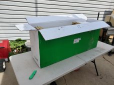
64 lbs
good packing
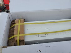
shipping package removed.
the Tall box is 31 inches tall
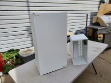
door open
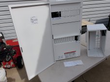
row for AC breakers - supporting 3 inverters
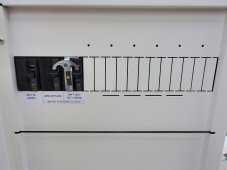
room for 3 250a breakers on the right of this row
along with 8 breakers for 4 charge controllers (60 amps prior to and 80 amps after each charge controller)
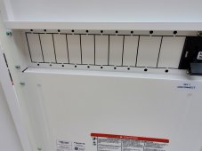
set of 3 60 amp AC breaks with interlock for AC IN and AC OUT
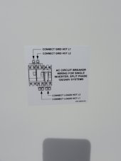
This how the layout will be, PDP on the right, Conduit Box under the forth coming XW Pro
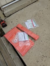
Wall plate and surge protector (extra) plate, and misc
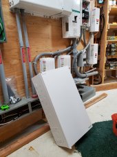
And finally where the PDP will be hung, upper right of of pic, replacing those 4 breakers shown
On the table in its box

64 lbs
good packing

shipping package removed.
the Tall box is 31 inches tall

door open

row for AC breakers - supporting 3 inverters

room for 3 250a breakers on the right of this row
along with 8 breakers for 4 charge controllers (60 amps prior to and 80 amps after each charge controller)

set of 3 60 amp AC breaks with interlock for AC IN and AC OUT

This how the layout will be, PDP on the right, Conduit Box under the forth coming XW Pro
Wall plate and surge protector (extra) plate, and misc

And finally where the PDP will be hung, upper right of of pic, replacing those 4 breakers shown

Last edited:
dougbert
Solar Addict
as I mentioned in a prior post, I am planning for 2 inverters, hence why I ordered the PDP.
But only one inverter first
But only one inverter first
Here in Florida, after the hurricane. No utility power.
Cannot get more than 500 watts of charge from AC2 (gen) into my batteries. Any ideas ?
Gen will automatically provide the house loads power plus 500 watts more for charging. But when my loads go down, I still cannot see more than the 500 w into batteries. When I have grid ac1 before the storm, I could charge 2 to 3 kw's.
dougbert
Solar Addict
The day and time to test your system was yesterday, sorry.When I try my older xw4548 it refuses to qualify the ac2 generator. The Combox webpage show AC2 voltages at 105/108 and together at 213v. Yet it says 0 Hz for freq. And always Qualifying, never Q-- good. And yet it worked ok a month ago.
dougbert
Solar Addict
Here in Florida, after the hurricane. No utility power.
Cannot get more than 500 watts of charge from AC2 (gen) into my batteries. Any ideas ?
Gen will automatically provide the house loads power plus 500 watts more for charging. But when my loads go down, I still cannot see more than the 500 w into batteries. When I have grid ac1 before the storm, I could charge 2 to 3 kw's.
I would start a new thread to increase visibility to the forum.
Sorry I can’t offer any further help.
Looking good, the Sch stuff does for sure look sexy, even in the back of a crappy travel trailer.. overkill? yes...... and great performance.
That does look great ! My SW4048 isn’t mounted half as nicely.
And IIRC your trailer is quite nice, under a shade structure of solar panels ?
dougbert
Solar Addict
Possibly a boring post today, but I spent some time on an upgrade, and I give some advice as to how to avoid the issues I went through
Back when my future wife bought this house in 1994 (built in 1930, addition in 1947) it had the old style wiring - Knob and tube wiring:

 www.squareone.ca
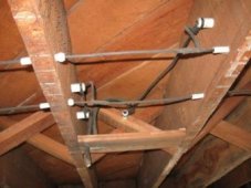
and almost all of the insulation had degraded and fallen off of the wire, leaving BARE wires throughout the house. Also the entire house was wired with just 4 circuits, protected by 4 fuses. OH MY. She and her son began the process of adding Romex wiring to boxes, etc, etc but didn't touch the fuse box
In 1995-1996 I came along and I began the task to swap out the fuse box and add a proper service entrance panel with meter base. Got the permit to do so. I got the "approved" plans and installed the service entrance and ran the SER wire from it to the fuse box area, getting ready to swap out the fuse box with a new Square D service panel.
First mistake I know I did: I should have put in a 24 (or bigger) breaker panel and not a Main Grid 12 breaker panel. Main breaker was 125 amp.
Second mistake: Should have done a 150amp main - oh well
Here is the then "new" service panel:
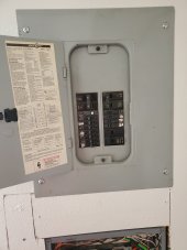
upper right 2 pole 40amp breakers goes to the oven in the kitchen
upper right 2 pole 30amp breaker goes to water heater receptical - no connected, using gas and PV to heat water
lower right 2 pole 60amp breaker goes to Solar Generator system and then to the main Critical Loads Panel (CLP) located downstairs in the basement.
Notice that all the 1 pole breakers are off, no circuits are presently connected to them.
NOTE: I could put in a 2 pole breaker here for a NEMA 14-50 receptical for an EV charge port someday, for GRID powered charging
Below is the main CLP in the basement (from a few weeks ago when I swapped out the BYPASS switch)
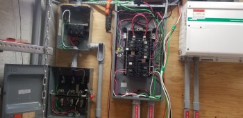
From the above Main CLP, there are 2 breakers on the lowest row, one (lower right) to a Sub CLP located below the Grid Service Panel and another (lower left) to a Sub CLP located in an out building.
Okay now to the work I did yesterday. When I installed these CLPs back in 2000 with the original solar system, I only ran 1 L1 power leg, since I only had a 120v inverter
Third mistake: should have run both L1 and L2 even when I would NOT use the L2 leg for twenty years
So to fix that, I ran the L2 wire through the conduit yesterday from the Main CLP to the house Sub CLP
From the Main CLP: (the black wire is the new one on the lower right breaker)
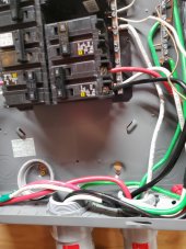
down to the raceway:
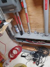
and up to the larger junction box, which is connected to the through the wall 2" conduit leading into the crawspace. From there conduit in crawspace comes up under the Sub CLP
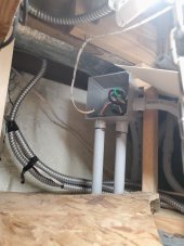
as shown here in the center conduit entrance in the Sub CLP:

which then is connected to power that Sub CLP as shown here:
The RED wire was already installed, while the BLACK wire was installed yesterday:

NOTICE: On the right side of the panel, is the "pass through" circuit that goes from the above Grid panel's 60 amp breaker thru this Sub CLP and carried in the conduit on the right, down to the basement connection. When I built it, that seemed the best way, but don't know if it "valid".
That was upgraded from 1 L1 leg to 2 legs, with the new L2 leg recently as well.
I expected the job to take 4 to 5 hours. It took 10 hours
Well, I am getting old and crawling multiple times into and out of the crawl space, inserting the fish line and pull wire took its toll and I rested many times - lol.
I admit I did remove the old conduit in the prior picture and that took time to do it right, extracting some length of the 3 wires and then re-pulling the 4 wires that last 6 feet back to the Sub CLP
So, my advice is to do the following:
Plan bigger than current requirements
even when pulling wire for 120v, pull 2 legs, L1 and L2
Maybe I should have used 1-1/4" conduit instead of the 1" I did
Install larger service panels than you think you need
When building a new home, Install the Main Grid Service Panel but also install a secondary Critical Loads Service Panel with most of the house circuits to this CLP - this allows for the addition of a solar generator between the two later if not immediately
Adding a new solar whole house generator to an existing house without such, makes things more difficult as most times there is not space to put the CLP and extending circuits is hard. In my existing house I upgrade I failed to do so as I was not yet Solar aware. That is why my Main CLP is in the basement and the Sub CLP is back up near the Grid Service Panel
as of today, my body hurts - time for another nap today
Back when my future wife bought this house in 1994 (built in 1930, addition in 1947) it had the old style wiring - Knob and tube wiring:

Knob & Tube Wiring | Identifying, Maintenance + More | Square One
Learn the basics of knob and tube wiring, including common issues, how to identify K&T wiring, maintenance, and insurance considerations.

and almost all of the insulation had degraded and fallen off of the wire, leaving BARE wires throughout the house. Also the entire house was wired with just 4 circuits, protected by 4 fuses. OH MY. She and her son began the process of adding Romex wiring to boxes, etc, etc but didn't touch the fuse box
In 1995-1996 I came along and I began the task to swap out the fuse box and add a proper service entrance panel with meter base. Got the permit to do so. I got the "approved" plans and installed the service entrance and ran the SER wire from it to the fuse box area, getting ready to swap out the fuse box with a new Square D service panel.
First mistake I know I did: I should have put in a 24 (or bigger) breaker panel and not a Main Grid 12 breaker panel. Main breaker was 125 amp.
Second mistake: Should have done a 150amp main - oh well
Here is the then "new" service panel:

upper right 2 pole 40amp breakers goes to the oven in the kitchen
upper right 2 pole 30amp breaker goes to water heater receptical - no connected, using gas and PV to heat water
lower right 2 pole 60amp breaker goes to Solar Generator system and then to the main Critical Loads Panel (CLP) located downstairs in the basement.
Notice that all the 1 pole breakers are off, no circuits are presently connected to them.
NOTE: I could put in a 2 pole breaker here for a NEMA 14-50 receptical for an EV charge port someday, for GRID powered charging
Below is the main CLP in the basement (from a few weeks ago when I swapped out the BYPASS switch)

From the above Main CLP, there are 2 breakers on the lowest row, one (lower right) to a Sub CLP located below the Grid Service Panel and another (lower left) to a Sub CLP located in an out building.
Okay now to the work I did yesterday. When I installed these CLPs back in 2000 with the original solar system, I only ran 1 L1 power leg, since I only had a 120v inverter
Third mistake: should have run both L1 and L2 even when I would NOT use the L2 leg for twenty years
So to fix that, I ran the L2 wire through the conduit yesterday from the Main CLP to the house Sub CLP
From the Main CLP: (the black wire is the new one on the lower right breaker)

down to the raceway:

and up to the larger junction box, which is connected to the through the wall 2" conduit leading into the crawspace. From there conduit in crawspace comes up under the Sub CLP

as shown here in the center conduit entrance in the Sub CLP:

which then is connected to power that Sub CLP as shown here:
The RED wire was already installed, while the BLACK wire was installed yesterday:

NOTICE: On the right side of the panel, is the "pass through" circuit that goes from the above Grid panel's 60 amp breaker thru this Sub CLP and carried in the conduit on the right, down to the basement connection. When I built it, that seemed the best way, but don't know if it "valid".
That was upgraded from 1 L1 leg to 2 legs, with the new L2 leg recently as well.
I expected the job to take 4 to 5 hours. It took 10 hours
Well, I am getting old and crawling multiple times into and out of the crawl space, inserting the fish line and pull wire took its toll and I rested many times - lol.
I admit I did remove the old conduit in the prior picture and that took time to do it right, extracting some length of the 3 wires and then re-pulling the 4 wires that last 6 feet back to the Sub CLP
So, my advice is to do the following:
Plan bigger than current requirements
even when pulling wire for 120v, pull 2 legs, L1 and L2
Maybe I should have used 1-1/4" conduit instead of the 1" I did
Install larger service panels than you think you need
When building a new home, Install the Main Grid Service Panel but also install a secondary Critical Loads Service Panel with most of the house circuits to this CLP - this allows for the addition of a solar generator between the two later if not immediately
Adding a new solar whole house generator to an existing house without such, makes things more difficult as most times there is not space to put the CLP and extending circuits is hard. In my existing house I upgrade I failed to do so as I was not yet Solar aware. That is why my Main CLP is in the basement and the Sub CLP is back up near the Grid Service Panel
as of today, my body hurts - time for another nap today
Last edited:
400bird
Solar Wizard
*Shudder*Possibly a boring post today, but I spent some time on an upgrade, and I give some advice as to how to avoid the issues I went through
Back when my future wife bought this house in 1994 (built in 1930, addition in 1947) it had the old style wiring - Knob and tube wiring:
Good work in getting rid of the knob and tube, looks like great progress!
Similar threads
- Replies
- 4
- Views
- 327
- Replies
- 95
- Views
- 2K
- Replies
- 2
- Views
- 295
- Replies
- 24
- Views
- 1K


