diy solar

diy solar

My first board build solar project

Jackamo

New Member
Joined
Mar 14, 2023
Messages
8
Location
Louisiana
I’m about ready to test this out. Maybe one of y’all experts can Let me know what I should change first. Be easy, it’s my first.
Its a Renogy Rover 60a controller. Giandel 3000w 24v inverter. 6 LG 280w panels and a chins 24v 100ah lifepo4 battery And a 10a 12v transformer. 2/0 battery to inverter wire and 6awg to controller. Called Renogy which stated that 80watts over on the panels is OK. I just have to set the controller parameters. I dont care for these breakers but they’re cheap and I can have several spares. I also have fuses but I like that I can trip these when needed. good or not?
Will run The garage first with a full size freezer and lights, then maybe on a friends houseboat.

oops, just saw the beginners and safety check sections, I guess this should be there. sorry, if I could move it I would.
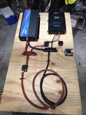
F0BEFBEC-1326-4794-B27A-AB92D5359939.jpeg
 
Last edited:
Welcome to the forum - lots of good info here. Your inverter in going to pull ~ 150 amps continuous (3000W / 24 volts / .85 efficiency conversion) but your battery's max discharge is only 100 amps, so you're going to need a second battery in parallel, which would also be a better fit for the amount of solar you have. What are the specs for your panels and how will you wire them? I'm assuming you won't be using all those panels if you take this on a houseboat?

I wouldn't trust those cheap breakers to keep your system safe, and you're going to at least need a big fuse close to the battery bank. There are some great info guides available available under the "Resources" tab - here are a couple that you may find helpful in designing your system:

DC Fuse/breaker guidelines
Solar array OCP
 
Good starter system! A couple thoughts:

The main breaker could be up sized, but your battery is going to limit you to 2400w. Not a huge deal, just limits you a bit.

No reason you can't add a proper fuse between the battery and breaker in the future. Same with a shunt in the future.

Still great for a first project! ?
 
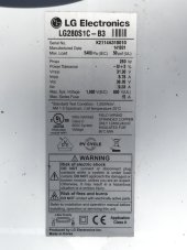
This is my panels. I actually have 26 of them (about 8 years old). I also have several fuses and a shunt that I didn’t use but can easily add a fuse at the battery. I do also plan to get another battery also. i plan to wire the panels in 3S2P for 1680W and about 115v.
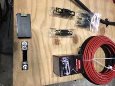
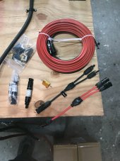
also here are panels and extras2FFFA227-0E28-4559-9100-AA17FC8637B6.jpeg1136F34F-7DAD-4841-83C7-53239456BA05.jpeg02D4F797-1418-4F5B-8842-8753E25674DA.jpeg
 
Last edited:
Those panels in 3S2P should work fine with your charge controller. If you have a shunt already, I would definitely suggest that you go ahead and wire it in - in addition to giving you SOC, it really helps with learning how things work with your first system.

I'd also suggest that you add a PV disconnect/2 pole DC breaker between the solar panels and the charge controller. Disconnecting the PV using the MC4 connectors under load is not a good idea, and you'll need to disconnect the PV any time you want to work on the system (can't switch off the battery connection without first disconnecting the PV).
The PV disconnect makes sense but also brings up another question. What happens to the controller if the breaker trips on the output side of the controller with the PV hot?
 
The PV disconnect makes sense but also brings up another question. What happens to the controller if the breaker trips on the output side of the controller with the PV hot?
Then the controller loses power and shuts off. If there's no load coming from the controller then the panels just sit there working on their tan. Remember, solar panels don't PUSH power into the system, they GIVE power when the system asks for it.
 
Then the controller loses power and shuts off. If there's no load coming from the controller then the panels just sit there working on their tan. Remember, solar panels don't PUSH power into the system, they GIVE power when the system asks for it.
Okay. I’ve read several times that connecting panels to a controller first would damage it.
 
Yes, so if somehow you popped that breaker, you'd need to shut off the panels before you powered the SCC back on, hence the suggestion on the breaker/disconnect to the panels.
 
looking at breakers now. 1680 watts divided by 115 volts should be about 15 amps. or does amps matter here since I have in-line fused pv connectors?
 
Yes amps matter as you don't want it tripping early. Also, there is a difference between AC and DC breakers so choose correctly for the job. Be sure any breaker you use is rated for the right voltage too. Many DC breakers are only rated up to 30v or so DC which is fine for your 12v battery, but not for your 120v panel string.
 
Yes amps matter as you don't want it tripping early. Also, there is a difference between AC and DC breakers so choose correctly for the job. Be sure any breaker you use is rated for the right voltage too. Many DC breakers are only rated up to 30v or so DC which is fine for your 12v battery, but not for your 120v panel string.
Yes, I would never go under, just didn’t know if going over would matter. I did not know that dc breakers were rated for different voltages though, so thanks for that ?
 
Yeah, the breakers and fuses are there to protect the wires more than the devices. So if you need to draw 100a regularly (for example numbers) you'd use breakers and wires sized for 120a. If for reason something shorted out and tried to draw 500a, the breaker would pop and prevent the wires from overheating and catching fire.
 
Added the PV breaker and have it running an upright freezer in the garage. So far I just have 3 of the 280 watt panels connected In series. Just want To see if that maintains. recorded 103voc about an hour before dark and It got dark out before I plugged in the freezer. controller was reading 26.4 volts and 100%. Freezer kicked on and was drawing 130watts On the inverter. Left it for a while checking periodically and saw 96% then 95% (on the controller) And freezer still running. Checked on the third trip and the freezer was off and the controller was reading that the battery was back up to 100% And 26.4 volts.
Is that normal?
also, i set the controller volts to 24 but I can’t change the parameters to coincide with 24v, the numbers are as if I’m using a 12v battery. The book basically says you have to double the numbers yourself. seems like and easy program for them to have it do the math for you. Strange.
 
Last edited:
Ignore the SOC readings on the charge controller - it's based off voltage which doesn't really work for LiFePO4, especially when the batteries are being charged or are under load. What you described is probably just an expected slight voltage drop when your freezer's compressor was on and pulling amps - when it cycles off the voltage may rise slightly - that's normal.

Use your shunt for SOC instead - you'll need to fully charge the battery and then sync the shunt to 100%. Renogy Rover SCCs are known to read voltage low - mine reads .25-3V low at higher voltages. Your shunt should be a more accurate way of seeing system voltage.

Are you using the default LiFePO4 settings in the Rover or did you set up a custom USER profile? You can use the Renogy BT app (not the DC home app) to set up a custom USER profile and change the parameters if you need to for your particular battery. Read more about that in this thread. As you said, the Rover requires you to input parameters as if it were a 12V system, and then it just doubles them. Also, if you set up custom parameters remember that the actual system voltage will likely be 0.25V higher than what the Rover thinks it is.

The Renogy Rovers definitely have some limitation/drawbacks, and if I had to do it again I'd buy a Victron, but once you get the Renogy set up okay and spend some time getting to know how it cycles it should work okay for you.


Yes, I need to figure this shunt out But this one gives you no way to mount it. I need to figure that out or get another one.
Thanks again.
 
Back
Top