diy solar

diy solar

1 Shunt 2 charge sources

philatio

New Member
Joined
Jun 2, 2021
Messages
137
My off grid and grid tied systems are separate except for the AC input to the off grid system to change the batteries and pass through the current to a critical loads panel. The off grid system is basically a partial home UPS system

I have 6 of the Signature Solar EG4-LL batteries in the 6 slot rack. There are times when there is not enough current to pass through to the critical loads panel to supply loads and charge the batteries at the same time. In a timely manner anyway.

I would like to utilize the EG4 18amp charger at these times. The charger can be hooked up by clipping the alligator clips to the battery rack bus bars and plugging it in. With the rack being full and the bus bars having heat shrink in places the battery cables don't attached to it, this is a difficult and not very timely way to do it. I am looking for a simpler method.

Would this be safe?

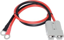
Attaching something like this to the one empty space of the positive & negative bus bars, then swapping out the alligator clips on the charger for the appropriate matching connectors? Might not be an Anderson type connector like this, but could be power pole or xt 90 type connectors or similar.
61L0A4k2PoL._AC_SL1500_.jpg

Any feedback would be greatly appreciated.
 
Last edited:
Yes, you can connect a charger to a battery bank. A couple of suggestions to think about
1) A breaker (or fuse) to protect the wire between then battery bank and the charger is a good idea. I use a breaker which doubles as on/off switch.
2) I hook my charger to the battery bus upstream of the shunt - so I can monitor overall current (including charge current) in/out of the battery.

Anderson connectors such as you show are typically good for 50a - plenty for an 18a charger. XT90 have a 90a rating? would work as well - https://components101.com/connectors/xt90-battery-connector Wire should be at least 12awg (20a max) and 10awg would be better if available / distance is more than a few feet. To verify, check the wire for warmth after prolonged charging and if 'hot to the touch' then use a larger wire.
Thanks for the feedback.

Do you mind providing even a rudimentary sketch?

Get all the current into and out of the battery was another issue.

My system currently is:

2awg cables from battery packs to rack bus bars

4/0 cable from battery rack bus bars to T Class Fuse to 250A DC breaker to inverter on the positive side.
4/0 cable from battery rack bus bars to shunt to 250A DC breaker to inverter on the negative side.

I am trying to visual the additional breaker as on off for the charger.

I am visualizing additional bus bars in there somewhere.

Thanks again
 
I changed the title to get more information on something said in the one and only replay to the original post.

How can one shut be set up with two charge sources? I source being the inverter and the other source being a battery charger. As stated in the only reply to the original post, they stated:
Yes, you can connect a charger to a battery bank. A couple of suggestions to think about
1) A breaker (or fuse) to protect the wire between then battery bank and the charger is a good idea. I use a breaker which doubles as on/off switch.
2) I hook my charger to the battery bus upstream of the shunt - so I can monitor overall current (including charge current) in/out of the battery.
If this is actually possible, which I have no reason at this point to doubt, what would this wiring diagram look like based on my setup as stated in my response post above with an EG4 6 battery rack filled and wired as follows:
2awg cables from battery packs to rack bus bars

4/0 cable from battery rack bus bars to T Class Fuse to 250A DC breaker to inverter on the positive side.
4/0 cable from battery rack bus bars to shunt to 250A DC breaker to inverter on the negative side.
Any input helping this noob out would be greatly appreciated.
 
Back
Top