diy solar

diy solar

100KWh DIY 18650 Powerwall in Germany

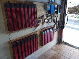
ready connected and running
50KWH_ready (1).jpg


50KWH_ready (2).jpg


50KWH_ready (3).jpg


now there are 50 KWh of total capacity up and running
50KWH_ready (4).jpg


50KWH_ready (5).jpg


Screenshot_20210218-153300.png


the next batterypacks with an estimated total of 20 KWh
50KWH_ready (7).jpg


I will try to complete this build within the next week
50KWH_ready (6).jpg


50KWH_ready (8).jpg
 
I contacted the seller on Aliexpress, D.YU.K.B / Dykbhuang Store (two names, same seller) and he agreed to refund the two defective BMS after sending it back

Yeah, I trust very few vendors on there to do that. I've bought them through Heltec before, and I've not had any issues. There are some people that had similar symptoms to you, but they were determined to be connection issues on the connector.

Would you still have a broken one by any chance? I've been trying to get my hands on one to figure out what the issue is and see if it can be fixed... If we find out the various modes in which it fails, and find solutions for it, this could be a very robust solution. I've also been thinking of replacing some components on it with better ones (like the FETS), but I would prefer to do that on a damaged one.
 
Two concerns: fire, and cold.

You've set up some "powerwall" in outbuildings which aren't so important, but one in a garage with your car. Is that attached to house?
At least one commercial lithium ion (not LiFePO4) powerwall (LG RESU-H) had a recall after several fires.
Our future electric code "NEC" is going to require battery systems that aren't lead-acid to have U.L. listing. But it will allow repurposed EV batteries if located more than 5' (about 2 meters) from the house. That way, if it does burn the house might survive.

I saw insulation inside one of your lockers. Does the BMS detect temperature and disable charging below 0 degrees C? Some BMS will allow inverter operation but if charging current is detected (on same electrical port) they disconnect. Others have separate charge and discharge ports. Some forum members also use heaters to keep their batteries warm enough. You probably don't have to worry about high charge rate. For someone with a small battery and enough PV to charge at 0.5C which is OK at room temperatures but in colder temperatures like 10 degrees C the battery should be charged at a lower rate.
 
as from the first one I am using 10mm Fermacell plates for the bottom, as separatores between the packs and for the intermediate floor

image_ztyyir.jpg


some SC16-6 ring terminals ans massice screws for connection

image_dayzrh.jpg


before adding the second row I have to connect the BMS because later I will not have enough space to reach the bottom row

image_frzdlr.jpg


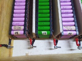
for easy and fast changings / mantainance I will not solder / screw the BMS cables, I am using alligator clips

image_bivynf.jpg


image_kpkgkx.jpg


the bottom row has 2cm space under this intermediate floor for air circulation

image_hedfop.jpg


image_vrihut.jpg


image_pqxrqh.jpg


mainly the same BMS as at the first 4,3KWh powerwall. The other is a JK-BD6A24S-10P (0,6A balancing current) which I changed later on to the 2A version. And it's the older, edged version without the big barcode on the top.
Now I am using directly the 2A version (JK-B2A24S-15P)

image_cfjlrm.jpg


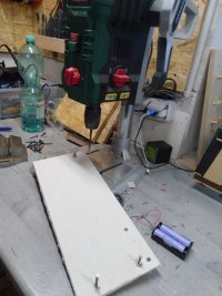
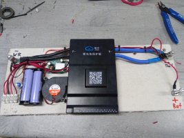
it will be mounted on a piece of fermacell plate

image_hffkwp.jpg


because there will be some mineral wool directly on the top of the BMS I glued some nuts as spacers below the BMS for better airflow and cooling

image_jsgwov.jpg


adding a radial cooler at the side (where a few air holes are situated) and choose the high of the cooler so that the airflow will go half to the holes and half below the BMS to cool the case

image_pgareb.jpg


adding two 18650s and a dip-switch to start the BMS. This is a bad thing of this BMS that you have to put a short impulse of 5V between the main B- and P- connectors, and not having a simple switch or so to start this thing up

image_zdvsnm.jpg


I need 12V for the temperature sensor display in the case top, and for the aircooler. In the first build I took the voltage directly from the akkupacks (main negative and three packs away the positive) and this caused in a permanent balancing of this tree packs.
Now I am using a little buck converter

image_wrcsjr.jpg


image_snwszt.jpg


adding the main wires

image_bqnlgs.jpg


image_qfiagc.jpg


finished

image_hlgnaq.jpg


image_ookcpk.jpg


image_pmpjzm.jpg
Fabulous story. Not yet done reading but have to say alligator clips = mistake.
 
Would you still have a broken one by any chance? I've been trying to get my hands on one to figure out what the issue is and see if it can be fixed..
oh, that's interesting, never heard of some failures before, I guess I will search the forum to find this cases.
My guess (not proofen):
when starting up the BMS while there is a voltage on the "P-" (maybe because you have two or more BMS in parallel or because the charge controller is running) this will cause a failure.
There is no warning documented which says you can't do this but hey - the documentation manual is horrible and lots of things are missing.
And yes I have another defect one with same sympthoms but I already send it to a guy I "met" via another DIY forum and he will look after it. If he can't fix it I will send it to you. Maybe this wil help lots of people out there.
btw.: I guess you're German? Here I a try to collect all information and data about the JKBMS I can get (it's my private website, no ads, no affiliates, no shit, just own experiences) -> Akkus - 14 aktiv Balancer BMS @ Mona-Stefan.de

Two concerns: fire, and cold.

You've set up some "powerwall" in outbuildings which aren't so important, but one in a garage with your car. Is that attached to house?
You are totally right, both are bad.
The less bad: cold. Yes the JKBMS do have temperature sensors (3 pcs) and stop charging at, hmm, I don't know exactly the default values, you can change it to your needs). But last winter I had no problems at all, the insulation keeps the batteries about 6°C warmer then outside.
And in summer the low current won't heat the batteries up so the fans at my first build are now not in use anymore
The more bad: fire. Yes I know about the danger of LiIon fire and as you already stated: one powerwall is at the garage and another in de the cellar.

there is a good video from Average Joe everybody should have viewed when building a DIY powerwall


The powerwall in the garage is designed completely open so I can check the cells quiet often, optically and from time to time with a IR camera so a failure can easily be discovered early.
LiIon do not explode or fire up from one moment to the next, it is a process of one cell (or more) which is dying and transform to a heater or gets shorted.
The other powerwall in the cellar is suited in an insulated metal locker which will, hopefully, prevend a fire outbreak as it is designed.

I have several security layers which I am using in my builds, one of them is a balancer with GUI where you can see what's going on. When it's balancing all the time in one cell-package this is the first indication of there is something wrong.
You can see my security concept here (you may use GTranslate) -> Akkus - 22 Sicherheitskonzept


Fabulous story. Not yet done reading but have to say alligator clips = mistake.
why?
For the balancing sleeves it's perfect because it makes servicing the batteriepacks more easier and faster. My alligator clips can handle 2A continous without getting warm, that's enough
 
after some research I only found two charge controllers which will fit the 65V.
- MakeskyBlue v118 and v119 (maybe the clone from PowMr can do as well) -> round about 160USD for the 60A version
- EPever Tracer AN series -> round about 300USD for the 6415AN = 60A version

Last weekend I found on eBay a 6415AN as customer return with full warranty for 100USD and so I bought this (and just selled the two "old" charge controller for about 80USD each :) )
IMG_20210320_094111.jpg


yesterday I installed the EPever. For this I had to do some modifications at the cables at the wall because the EPever is much bigger
IMG_20210320_095016.jpg


now the batteries can for the first time be fully charged
IMG_20210320_124713_7.jpg


to access all parameter of the EPever you'll need the additional MT50 Display (round about 18 USD).
And now the system is running in my preferred voltage range from 52,8V to 65V which is single cell voltage 3,30V to 4,05V
IMG_20210320_124724_3.jpg


and I added a voltmeter with shunt to the system so I can see what's going on with the batteries without connecting to the bluetooth app first. It's at the exakt position where I look first when I leave my car when coming home.
KW10_Garagendach_PV_82.jpg


Now the garage is ready and I can charge the car with the sun


here's a video I made about the DIY 18650 powerwall at the garage, you may activate subtitles


and here part two with some modifications with an voltage-controlled automatic transfer switch
 
Last edited:
the last two weeks I finished my powerwall project. On the ToDO list:

28 batterie packs 60p

phoca_thumb_l_KW09_DIY_18650_Powerwall_Spind_fertig_01.jpg


At the end it's more effort then the bigger 120p packs because of twice of the amount of busbars
phoca_thumb_l_KW09_DIY_18650_Powerwall_Spind_fertig_02.jpg


phoca_thumb_l_KW09_DIY_18650_Powerwall_Spind_fertig_03.jpg


I solder the fuse wire in one piece and at the end I cut the unnecessary pieces
phoca_thumb_l_KW09_DIY_18650_Powerwall_Spind_fertig_04.jpg


almost ready
phoca_thumb_l_KW09_DIY_18650_Powerwall_Spind_fertig_05.jpg


phoca_thumb_l_KW09_DIY_18650_Powerwall_Spind_fertig_06.jpg


just need to solder the fuse-wires to the busbars
phoca_thumb_l_KW09_DIY_18650_Powerwall_Spind_fertig_07.jpg


phoca_thumb_l_KW09_DIY_18650_Powerwall_Spind_fertig_08.jpg


next step: balancing all the packs
phoca_thumb_l_KW09_DIY_18650_Powerwall_Spind_fertig_09.jpg


pretty dangerous so close together, I do recommend not to do so
phoca_thumb_l_KW09_DIY_18650_Powerwall_Spind_fertig_10.jpg


for me it works well but I_ve done this just several times
phoca_thumb_l_KW09_DIY_18650_Powerwall_Spind_fertig_11.jpg


on the other side there are sitting the 120p packs, but they need some time to balance too
phoca_thumb_l_KW09_DIY_18650_Powerwall_Spind_fertig_12.jpg


after 48h of balancing the 60p are balanced and ready for installation
phoca_thumb_l_KW09_DIY_18650_Powerwall_Spind_fertig_23.jpg


they will support the 11KWh system at the pigsty
phoca_thumb_l_KW09_DIY_18650_Powerwall_Spind_fertig_25.jpg


phoca_thumb_l_KW09_DIY_18650_Powerwall_Spind_fertig_26.jpg


all wires are 16mm² as well as the busbars
phoca_thumb_l_KW09_DIY_18650_Powerwall_Spind_fertig_27.jpg


I decided to take the BMS plate out again and make a modification
phoca_thumb_l_KW09_DIY_18650_Powerwall_Spind_fertig_28.jpg


I want to add a external voltmeter to the locker so I can see the battery status while walking past the locker without connecting to the bluetooth app, so I have to add a shunt
phoca_thumb_l_KW09_DIY_18650_Powerwall_Spind_fertig_29.jpg


then back again with the bms and with all battery packs. Two systems with 14s60p each fits into one compartment
phoca_thumb_l_KW09_DIY_18650_Powerwall_Spind_fertig_30.jpg


next is to customize the bms wiring harness
phoca_thumb_l_KW09_DIY_18650_Powerwall_Spind_fertig_32.jpg
 
on the right side the two older systems, left the two new with identical capacity
phoca_thumb_l_KW09_DIY_18650_Powerwall_Spind_fertig_33.jpg


at the app there are four systems now
phoca_thumb_l_KW09_DIY_18650_Powerwall_Spind_fertig_34.png


because the voltages didn't fit there is a huge current at the moment of adding the two new systems to the older ones
phoca_thumb_l_KW09_DIY_18650_Powerwall_Spind_fertig_35.png


4,5V difference.
But it doesn't matter, all cables and BMS are good for 60A continous current
phoca_thumb_l_KW09_DIY_18650_Powerwall_Spind_fertig_36.png


after installing the battery packs I want to add a voltmeter too
phoca_thumb_l_KW09_DIY_18650_Powerwall_Spind_fertig_37.jpg


the "Dremel" clone works well with the good grind discs from a dental supply
phoca_thumb_l_KW09_DIY_18650_Powerwall_Spind_fertig_38.jpg


on this picture the display is with default settings therefore the battery status is wrong, you have to manually set the max and min voltage first
phoca_thumb_l_KW09_DIY_18650_Powerwall_Spind_fertig_42.jpg


phoca_thumb_l_KW09_DIY_18650_Powerwall_Spind_fertig_43.jpg


phoca_thumb_l_KW09_DIY_18650_Powerwall_Spind_fertig_44.jpg


last step is to complete the fire safe insulation. Now, the system in the pigsty is finished
phoca_thumb_l_KW09_DIY_18650_Powerwall_Spind_fertig_40.jpg


next step: the other system at the garden shed
phoca_thumb_l_KW09_DIY_18650_Powerwall_Spind_fertig_45.jpg


to the already existing two systems of 14s120 there comes another 14s120p
phoca_thumb_l_KW09_DIY_18650_Powerwall_Spind_fertig_46.jpg


phoca_thumb_l_KW09_DIY_18650_Powerwall_Spind_fertig_47.jpg


I add a shunt too
phoca_thumb_l_KW09_DIY_18650_Powerwall_Spind_fertig_53.jpg


it's designed for 200A. Each battery system will be limited to 120A
phoca_thumb_l_KW09_DIY_18650_Powerwall_Spind_fertig_55.jpg


phoca_thumb_l_KW09_DIY_18650_Powerwall_Spind_fertig_56.jpg


cables and busbars in 35mm² copper
phoca_thumb_l_KW09_DIY_18650_Powerwall_Spind_fertig_58.jpg


the bms wiring harness has to be extended
phoca_thumb_l_KW09_DIY_18650_Powerwall_Spind_fertig_59.jpg


phoca_thumb_l_KW09_DIY_18650_Powerwall_Spind_fertig_61.jpg


just stuck together, without some cable management at this point
phoca_thumb_l_KW09_DIY_18650_Powerwall_Spind_fertig_62.jpg
 
here we go, the three systems inside the locker at the garden shed

phoca_thumb_l_KW09_DIY_18650_Powerwall_Spind_fertig_63.png


the moment of connecting

phoca_thumb_l_KW09_DIY_18650_Powerwall_Spind_fertig_64.png


now that it works I can do some cable management

phoca_thumb_l_KW09_DIY_18650_Powerwall_Spind_fertig_65.jpg


phoca_thumb_l_KW09_DIY_18650_Powerwall_Spind_fertig_66.jpg


phoca_thumb_l_KW09_DIY_18650_Powerwall_Spind_fertig_67.jpg


phoca_thumb_l_KW09_DIY_18650_Powerwall_Spind_fertig_68.jpg


phoca_thumb_l_KW09_DIY_18650_Powerwall_Spind_fertig_69.jpg


cables for the voltmeter

phoca_thumb_l_KW09_DIY_18650_Powerwall_Spind_fertig_70.jpg


phoca_thumb_l_KW09_DIY_18650_Powerwall_Spind_fertig_72.jpg


and the front insulation

phoca_thumb_l_KW09_DIY_18650_Powerwall_Spind_fertig_73.jpg


now three of a total of four compartments are fully equipped (the smaller locker in the pigsty has one compartement left too)

phoca_thumb_l_KW09_DIY_18650_Powerwall_Spind_fertig_74.jpg


So, now at this point I set my powerwall project on "pause" because weather is getting better and I have lots of plans for my garden.

At the end here are some facts summed up
  • 75KWh of usable capacity
  • 10.800 cells 18650 from used and defective laptop and ebike batteries
  • voltage range single cells: 3,30 - 4,05V
  • voltage range 14s systems: 46,0 - 56,6V (exception: 16s system at the garage)
  • maximum total output power: 16,4KW
  • duration of this project: 11 month

plans for summer:
  • increase the amount of photovoltaic modules to improve solar income especially in winter

plans for next winter:
  • to complete both lockers and increase the total capacity to 100kWh (cells are still there and waiting)
 
btw.: I guess you're German? Here I a try to collect all information and data about the JKBMS I can get (it's my private website, no ads, no affiliates, no shit, just own experiences) -> Akkus - 14 aktiv Balancer BMS @ Mona-Stefan.de

Not German, but I speak the language. I'll check out the site!

when starting up the BMS while there is a voltage on the "P-" (maybe because you have two or more BMS in parallel or because the charge controller is running) this will cause a failure.

I have two running in parallel on the same bus bar in this fashion for quite some time now without issues.

Keep me posted on the broken one - if you get it back unfixed: I'm in Finland so shipping should be straight forward (and I'll pay for it).
 
it's designed for 200A. Each battery system will be limited to 120A
phoca_thumb_l_KW09_DIY_18650_Powerwall_Spind_fertig_55.jpg

Is that a shunt? Stack of washers and nuts in current-carrying path is bad.
The cable terminals should be pressed in direct contact with shunt terminals. If anything in between, needs to be good conductor.
 
why?
For the balancing sleeves it's perfect because it makes servicing the batteriepacks more easier and faster. My alligator clips can handle 2A continous without getting warm, that's enough

(... but have to say alligator clips = mistake.)

Cheap steel alligator clips make poor contact. They've been a problem for people charging/balancing at higher current.
That won't be an issue for BMS monitor/balance current. But they could rust due to humidity and become open.
Better would be copper clips. (like usual, listings that say "copper" aren't necessarily; magnet will tell the truth.)

You could instead add a wire with connector.
 
I have two running in parallel on the same bus bar in this fashion for quite some time now without issues.
sorry, I did not wrote clearly.
I meant: running in parallel is not the problem, but starting the bms via a 5V impulse on B- and P- while there is some external voltage on the P- too may damage the bms. I guess you have to cut the external voltage before starting the bms.

Is that a shunt? Stack of washers and nuts in current-carrying path is bad.
you are totally right, at this time I disassembled the shunt because the washer stack gets too hot
file.php


You could instead add a wire with connector.
that's a good idea, thanks
 
Because I do shift work I can't always charge directly at my photovoltaic and so with the powerwall this should save a lot of money.
btw: electric prices in Germany are the highest in the whole world with 0,39USD per KWh
Wow if it was that high here every square mm of my property would be covered in solar panels. Electricity here is only about $0.11/kwh and they only pay about half that if you feed to the grid.
 
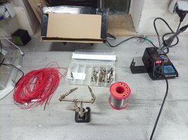
I solder the fuse wires to the cells with a cheap solder-station from eBay. For me 370°C on the positive side and 390°C on the negative side seems to be perfect. At low temperatures about zero degrees at my garage where I am working you can add 5°C for soldering better
KW52_DIY_Tesla-Powerwall_16s100p_Mounting_System_106.jpg

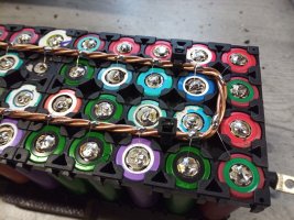
to solder the fusewire to the busbars I am using a 150W iron from Ersa, the 150S. I tried two cheap chinese irons but the tipp will melt faster than a candle and hinders me all the way in my working progress.
KW52_DIY_Tesla-Powerwall_16s100p_Mounting_System_107.jpg

as solder wire I am using one with Sn60% Pb40% with fluxcore. Works very well without any cold soldering points. I need not more then 1 second per solder point at the cells and 2 seconds at the busbars.
KW52_DIY_Tesla-Powerwall_16s100p_Mounting_System_108.jpg

here is a horrible boring video but without timelaps you can have a look at the working speed


KW52_DIY_Tesla-Powerwall_16s100p_Mounting_System_110.jpg

after finishing the packs I charge them up to 4,05V...
KW52_DIY_Tesla-Powerwall_16s100p_Mounting_System_111.jpg

...and test the real capacity between 4.05V and 3,30V with the modified DL24 electronic load at a discharge current of 15A.
The all have about 500Wh
1610521166743.jpeg

to complete the installation I build some little BMS-holder
KW53_Aiways_U5_DIY_Tesla-Powerwall_16s100p_1.jpg

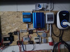
because I build up two powerwalls in parallel I am using two BMS. This is the small one with 60A/120A max and integrated active balancer with 0,6A balancing current.
KW53_Aiways_U5_DIY_Tesla-Powerwall_16s100p_2.jpg

the bigger, black one on the left can handle 150A/300A with 2A balancing current
KW53_Aiways_U5_DIY_Tesla-Powerwall_16s100p_4.jpg

some connector-plates
KW53_Aiways_U5_DIY_Tesla-Powerwall_16s100p_3.jpg

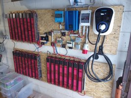
now it is nearly done. The two banks on the left are one system with 8KWh and the one on the right is another 16s50p system with...
KW53_Aiways_U5_DIY_Tesla-Powerwall_16s100p_5.jpg

...I build as a devided pack-design to get the same size as the first powerwall
KW01_DIY_18650_Powerwall_verkabeln_035.jpg

KW53_Aiways_U5_DIY_Tesla-Powerwall_16s100p_6.jpg

KW53_Aiways_U5_DIY_Tesla-Powerwall_16s100p_7.jpg

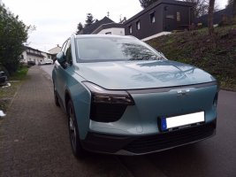
then, the last days in the old year I got my new car I am waiting for several month. It's an
Aiways U5 full electric car with 150KW engine and 63KWh battery (good for a range of 400KM)
KW53_Aiways_U5_DIY_Tesla-Powerwall_16s100p_23.jpg

KW53_Aiways_U5_DIY_Tesla-Powerwall_16s100p_33.jpg

KW53_Aiways_U5_DIY_Tesla-Powerwall_16s100p_34.jpg

with a total of 8 cameras and all electronic assistance systems you can get this time including autonomous driving
KW53_Aiways_U5_DIY_Tesla-Powerwall_16s100p_45.jpg

Because I do shift work I can't always charge directly at my photovoltaic and so with the powerwall this should save a lot of money.
btw: electric prices in Germany are the highest in the whole world with 0,39USD per KWh
.35 kwh bahamas? we are not to far behind
 
Thanks for taking the time to document and share - that is an impressive effort.
 
The internal resistance and voltage sparks of the batteries produced by different manufacturers will bring very big risks to the use of battery packs. Including explosion and burning
Can you please explain that?

In my opinion different manufacturers won't be any problem, electricity doesn't know about brands ;-)

And different internal resistances will cause that the cells with lower values will have more load than the ones with higher resistance.
Same thing with different capacities (which mostly is directly correlating with the Ri). The cells with higher capacity will cover more load than the weaker ones.
That's the reason why I sorted my packs in that way that the high-capacity cells are in the area next to the busbar main-connectors, and the more distance to the connectors, the less capacity they have.

Since they are in parallel, there will be no sparks and the voltage in one pack is the same at all time.
 
these effects appear when combining small amounts of cells in parallel befor connecting them serial - in combination with huge currents.

I don't do both of this.
I am using huge amounts of cells in parallel (60pcs or 120p per system, and because I have several complete 14s systems parallel there are effectively 360 cells in parallel.
That in combination with a tiny current of 0,1 - 0,5A max per cell will not cause any overcharge / overdischarge in a single cell.
And a bms will take care about the voltage of the parallel packs so that a drifting voltage will not harm the system. In addition a balancer will avoid voltage differences between the packs.

You can trust me too, this system is running perfectly since last year and approved by many DIY-people all over the world who are using very similar systems.

small update:
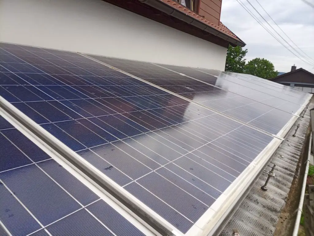
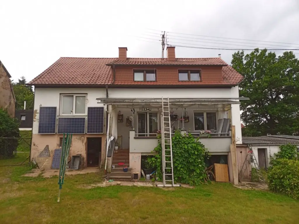
some more pv modules to add another 1,65kWp on the roof of the balcony
phoca_thumb_l_KW28-Balkon-Solar_fertig_Hochbeete2_02.jpg


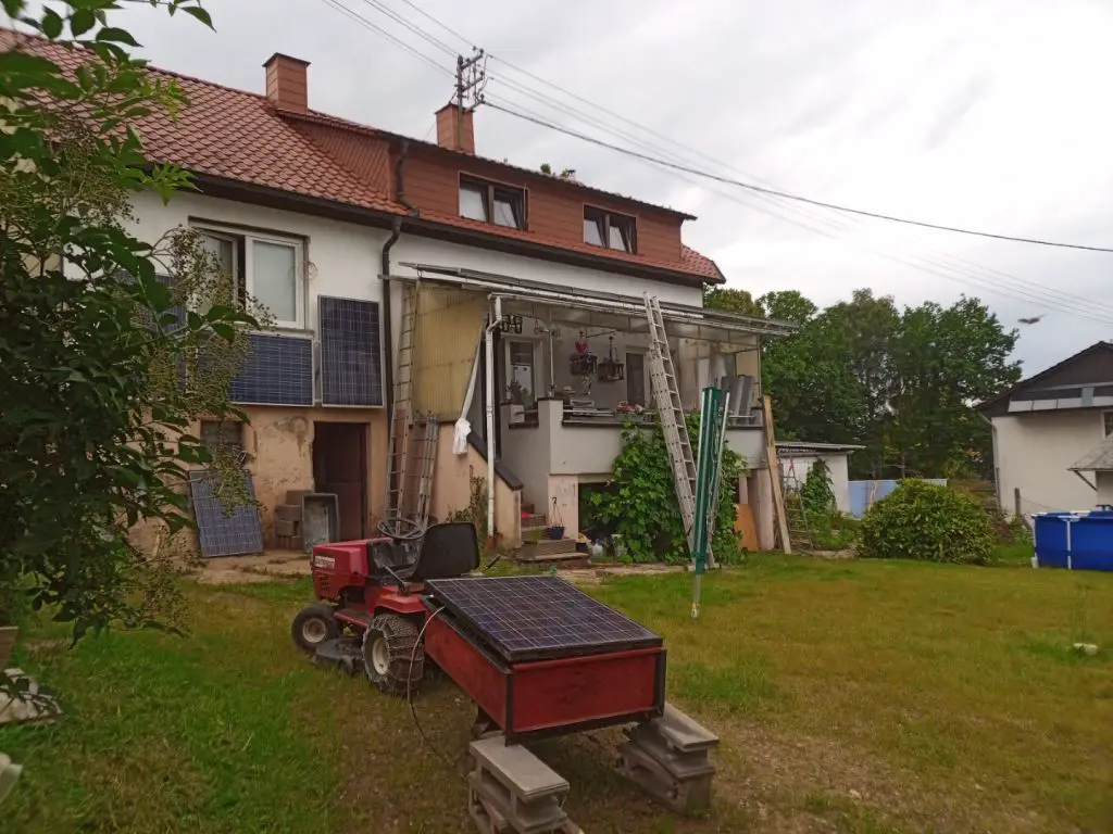
and another 600 watts at the wall
phoca_thumb_l_KW28-Balkon-Solar_fertig_Hochbeete2_09.jpg


and no, the lawn mower is not solar-electric ;)
this is just an old, defective module which protects the content of the trailer against rain

phoca_thumb_l_KW28-Balkon-Solar_fertig_Hochbeete2_10.jpg
 
Last edited:
some more pv modules to add another 1,65kWp on the roof of the balcony
phoca_thumb_l_KW28-Balkon-Solar_fertig_Hochbeete2_02.jpg

Does the sun ever get high enough that roof casts a shadow on them?
If so, I would rather see more tilt, rails from lower edge of awning up to eaves of roof.
 
Back
Top