I guess we’d need to confirm if the inspector specified is the ground needed for AC or DC side? Also where is the inverter mounted? If inside then the ground wire from the inverter to your main panel is adequate when you hooked up the grid feed breaker. (That was the case for me)So, when I do get this rod in the ground, I assume I run a #6 bare wire from the Solark ground bar through the same conduit and hole to the outside for the AC disconnect.
Then out the bottom of the AC disconnect box down the wall in conduit to the dirt. From there I go under the dirt a few inches over to the new ground rod.
I run another #6 bare wire under the dirt from the new ground rod to the existing ground rod.
That's it right?
Some inverters have 2 separate grounds one for AC and one for DC but I think the Solark only has one ground bar marked with red below.
View attachment 41735
You are using an out of date browser. It may not display this or other websites correctly.
You should upgrade or use an alternative browser.
You should upgrade or use an alternative browser.
10K PV and Solark Install
- Thread starter ArthurEld
- Start date
ArthurEld
Solar Wizard
He's having me install a 2nd ground rod for the inverter in case the solar panels get hit by lightning.I guess we’d need to confirm if the inspector specified is the ground needed for AC or DC side?
InsideAlso where is the inverter mounted?
I have a ground wire from the inverter to the main breaker panel now. I'm not sure if that needs to stay connected after I connect the inverter to the new ground rod.If inside then the ground wire from the inverter to your main panel is adequate when you hooked up the grid feed breaker. (That was the case for me)
I will call the inspector before I install the rod. I think this is a common procedure. And it is safer.
Hedges
I See Electromagnetic Fields!
- Joined
- Mar 28, 2020
- Messages
- 20,577
I don't think the 6 awg bare copper is supposed to be direct-buried, especially shallow.
I have short hops in the air tying all pipes, conduit, rod together.
Maybe it is supposed to run through a conduit to join the rods 6' apart (I'm not sure).
I run ground together with its associated conductors in rigid conduit, but when running ground by itself I avoid ferrous conduit (although I have not been able to measure higher inductance due to the magnetic material.)
ArthurEld
Solar Wizard
I thought I read it was supposed to be bare but I will check again. I am fairly sure it doesn't need conduit in the dirt but does if it goes up the wall.I don't think the 6 awg bare copper is supposed to be direct-buried, especially shallow.
I have short hops in the air tying all pipes, conduit, rod together.
Maybe it is supposed to run through a conduit to join the rods 6' apart (I'm not sure).
I run ground together with its associated conductors in rigid conduit, but when running ground by itself I avoid ferrous conduit (although I have not been able to measure higher inductance due to the magnetic material.)
6 awg is minimum.
I might not be able to get the ground wire through the existing conduit to go from the inverter inside to the ground rod outside.
Maybe I should just run a separate conduit and make another hole to the outside.
Hmmm not sure why unless your pv array is not grounded already at the array...? Is it? If not then that is a definite requirement, catch a lighting surge before it burns up the wire to the house...He's having me install a 2nd ground rod for the inverter in case the solar panels get hit by lightning.
Inside
I have a ground wire from the inverter to the main breaker panel now. I'm not sure if that needs to stay connected after I connect the inverter to the new ground rod.
I will call the inspector before I install the rod. I think this is a common procedure. And it is safer.
I would double check with sol-ark on his request. The last place I would want to deal with a surge is at the inverter, it’ll be too late
ArthurEld
Solar Wizard
The PV ground goes to the Solark per the permit plan from AltE. It's working that way now.Hmmm not sure why unless your pv array is not grounded already at the array...? Is it? If not then that is a definite requirement, catch a lighting surge before it burns up the wire to the house...
Maybe the PV ground is supposed to go straight to the new grounding rod.
I will check with Solark.I would double check with sol-ark on his request. The last place I would want to deal with a surge is at the inverter, it’ll be too late
ArthurEld
Solar Wizard
Here is what the inspection correction notice says-
"Need to have grounding electrode system up to current 250 code per 690.47 NEC
Two rods 6' apart. GEC needs to be continuous NEC 250 .52-.53"
I spent some time looking up the codes and they are ugly and unclear.
Everyone agrees these codes are unclear and that inspectors often misinterpret them.
My inspector is requiring me to add another ground rod. I suspect it is a waste of time.
But I am going to do it. It probably won't hurt anything.
I'll see if Solark has some input.
I guess I am going to also have to ask the inspector what exactly he wants me to connect to this new ground.
This GEC continuous thing seems odd too. He mentioned irreversible clamping.
Maybe he does just enjoy making me jump through hoops.
They know I will have one hell of a system once it's approved. But they don't understand it well.
The solar installers and electricians don't understand this stuff well either. That makes a bunch of us that don't understand it well.
I can expect the electric company to give me a bunch of hoops too.
Agree wrt interpretation and enforcement. The NEC book year (08, 11, 14, 17 or 20) your town/city has adopted is key since the language and requirements have changed ever version since 08 for this area. In our neck of the woods there are neighboring towns where they are still on the 14 book while our town follows the 17.Here is what the inspection correction notice says-
"Need to have grounding electrode system up to current 250 code per 690.47 NEC
Two rods 6' apart. GEC needs to be continuous NEC 250 .52-.53"
I spent some time looking up the codes and they are ugly and unclear.
Everyone agrees these codes are unclear and that inspectors often misinterpret them.
My inspector is requiring me to add another ground rod. I suspect it is a waste of time.
But I am going to do it. It probably won't hurt anything.
I'll see if Solark has some input.
I guess I am going to also have to ask the inspector what exactly he wants me to connect to this new ground.
This GEC continuous thing seems odd too. He mentioned irreversible clamping.
Maybe he does just enjoy making me jump through hoops.
They know I will have one hell of a system once it's approved. But they don't understand it well.
The solar installers and electricians don't understand this stuff well either. That makes a bunch of us that don't understand it well.
I can expect the electric company to give me a bunch of hoops too.
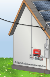
Here is a small recap of this NEW section that could be helpful (also the Mike Holt site is pretty good for reference):
690.47 Buildings or Structures Supporting a PV Array.
The building or structure supporting the PV array requires a grounding electrode.
www.electricallicenserenewal.com
Good luck.
ArthurEld
Solar Wizard
This area is still on NEC 2014 for some things but they are adding parts of NEC 2017Agree wrt interpretation and enforcement. The NEC book year (08, 11, 14, 17 or 20) your town/city has adopted is key since the language and requirements have changed ever version since 08 for this area. In our neck of the woods there are neighboring towns where they are still on the 14 book while our town follows the 17.
Here is a small recap of this NEW section that could be helpful (also the Mike Holt site is pretty good for reference):
690.47 Buildings or Structures Supporting a PV Array.
The building or structure supporting the PV array requires a grounding electrode.www.electricallicenserenewal.com
Good luck.
Besides that, the inspector can interpret the code any way he wants to.
The picture in your link just shows the new rod bonded to the existing rod with no other connections.

Correct, that is why i referenced it. I'd hate to risk the inverter to someone interpreting the code one way where it may conflict with the manual that has strict warnings of how to wire the system. (in my 12k version there is no wire diagram that highlights any DC or AC ground to earth, only AC ground back to the ac panel).This area is still on NEC 2014 for some things but they are adding parts of NEC 2017
Besides that, the inspector can interpret the code any way he wants to.
The picture in your link just shows the new rod bonded to the existing rod with no other connections.
View attachment 41845
ArthurEld
Solar Wizard
I won't drive in the rod or connect anything until I am clear about this.
I still have to call 811 and have them mark the ground before I can do anything.
The info I read about separate grounds might be wrong. From what I read people ground solar panels in a lot of different ways.
I still have to call 811 and have them mark the ground before I can do anything.
The info I read about separate grounds might be wrong. From what I read people ground solar panels in a lot of different ways.
Hedges
I See Electromagnetic Fields!
- Joined
- Mar 28, 2020
- Messages
- 20,577
Two rods for better contact to earth, lower resistance apparently.
Irreversibly bonded - I think they don't want a screw to disconnect the wire splice (although a bolt could remove clamp from rod.)
Single wire threaded through one to the other is one way. There are materials which combust and perform brazing. You'd think a crimp butt splice (rated for the environment) would also be adequate.
ArthurEld
Solar Wizard
A crimp butt splice is adequate. But I think that requires a special crimping tool. The ones I saw are expensive.Two rods for better contact to earth, lower resistance apparently.
Irreversibly bonded - I think they don't want a screw to disconnect the wire splice (although a bolt could remove clamp from rod.)
Single wire threaded through one to the other is one way. There are materials which combust and perform brazing. You'd think a crimp butt splice (rated for the environment) would also be adequate.
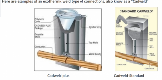
Maybe this would work-

ArthurEld
Solar Wizard
GXMnow
Solar Wizard
- Joined
- Jul 17, 2020
- Messages
- 2,709
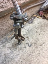
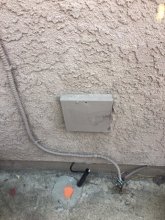
Here are some pics of my ground install.


The grounding wire is one single run from the panel, goes through the clamp on this first rod, and goes down the wall to the clamp n the second rod. I added the second clamp on the first rod which will take the ground wire from my DC charge controller. I tried to get the wire to show, but the iPhone cam was not quite good enough to get it in the shadow. The hole in the sidewalk was actually a bit larger than the rod, but they left a lot of the dust from drilling the concrete, and it filled around the rod and after rain it has cured almost like new concrete right up to the rod again. The black wire in the second picture is the replacement cable line for my Spectrum internet. They had to core through the sidewalk and run a new line. Something AT&T refused to do. The orange and purple paint dots on the ground are just 2 of the marks the utility locators put down as they traced all of the underground lines there. The orange is obviously the cable line, they put a dot every 2 feet or son along the run. The purple is the old AT&T phone lines. At this point, the yellow for the gas line is about 2 feet out from the wall, just out of the bottom of the picture.


The grounding wire is one single run from the panel, goes through the clamp on this first rod, and goes down the wall to the clamp n the second rod. I added the second clamp on the first rod which will take the ground wire from my DC charge controller. I tried to get the wire to show, but the iPhone cam was not quite good enough to get it in the shadow. The hole in the sidewalk was actually a bit larger than the rod, but they left a lot of the dust from drilling the concrete, and it filled around the rod and after rain it has cured almost like new concrete right up to the rod again. The black wire in the second picture is the replacement cable line for my Spectrum internet. They had to core through the sidewalk and run a new line. Something AT&T refused to do. The orange and purple paint dots on the ground are just 2 of the marks the utility locators put down as they traced all of the underground lines there. The orange is obviously the cable line, they put a dot every 2 feet or son along the run. The purple is the old AT&T phone lines. At this point, the yellow for the gas line is about 2 feet out from the wall, just out of the bottom of the picture.
ArthurEld
Solar Wizard
Thanks GXMnow.Here are some pics of my ground install.
View attachment 41885 View attachment 41886
The grounding wire is one single run from the panel, goes through the clamp on this first rod, and goes down the wall to the clamp n the second rod. I added the second clamp on the first rod which will take the ground wire from my DC charge controller. I tried to get the wire to show, but the iPhone cam was not quite good enough to get it in the shadow. The hole in the sidewalk was actually a bit larger than the rod, but they left a lot of the dust from drilling the concrete, and it filled around the rod and after rain it has cured almost like new concrete right up to the rod again. The black wire in the second picture is the replacement cable line for my Spectrum internet. They had to core through the sidewalk and run a new line. Something AT&T refused to do. The orange and purple paint dots on the ground are just 2 of the marks the utility locators put down as they traced all of the underground lines there. The orange is obviously the cable line, they put a dot every 2 feet or son along the run. The purple is the old AT&T phone lines. At this point, the yellow for the gas line is about 2 feet out from the wall, just out of the bottom of the picture.
I think it might be easier for me to splice a piece on to the wire that is there.
But I will take a look to see how hard it would be to replace the wire.
I hate that stupid rod sticking out.
svetz
Works in theory! Practice? That's something else
Mike Holt explains why 690.47d needs to immediately be removed from the code (why multiple grounds can be bad). Long video but he explains it well. If it's a concern for your area (e.g., don't you live in one of the lightening capitals of the world?), think about how to undo it after the inspector leaves. Auxiliary grounding electrodes (like for a generator) are exempt and don't need to meet the 25 ohm rule or tied to the main ground - but you have to make it match up to what your inspector wants to get passed.
Last edited:
ArthurEld
Solar Wizard
I saw the video. But it is old and probably a million people have done it since then.Mike Holt explains why 690.47d needs to immediately be removed from the code (why multiple grounds can be bad). Long video but he explains it well. If it's a concern for your area (e.g., don't you live in one of the lightening capitals of the world?), think about how to undo it after the inspector leaves. Auxiliary grounding electrodes (like for a generator) are exempt and don't need to meet the 25 ohm rule or tied to the main ground - but you have to make it match up to what your inspector wants to get passed.
I honestly have no understanding of this 2nd ground and probably never will.
If I decide it is unsafe, I will disconnect it. Irreversible crimp my eye!
ArthurEld
Solar Wizard
I checked the existing ground wire and it doesn't look easy to replace.
So, I guess I'll try the Cadweld. My existing rod is about 8" from the wall so it's in the way.
Having this wire T on the top of it isn't going to help matters.
So, I guess I'll try the Cadweld. My existing rod is about 8" from the wall so it's in the way.
Having this wire T on the top of it isn't going to help matters.
Similar threads
- Replies
- 35
- Views
- 992
- Replies
- 2
- Views
- 240
- Replies
- 13
- Views
- 556


