diy solar

diy solar

16S, 272Ah Lishen + TinyBMS - Build Thread

About the cells. Seems I've had a similar issue with Lishen cells from Shenzhen Xuba. The cells definitely don't look new . Not even 1 cell looks anywhere near what could be considered newish. 3/20 cells have dents, 3/20 cells the wrapping doesn't cover the entire cell. All the terminals are marked/scratched. Chatting with the supplier now but yeah, had higher expectations. Maybe both suppliers got the same batch of cells...

Sorry for the thread jacking... :)
 
Just looked at the specs and .5v drop is normal for this one. Huh, big drop for a shotty. My bad. Man I bet they generate a ton of heat. If they're the ones I linked to a few weeks ago I profoundly apologize as I made a recommendation but didnt read the specs on it - I just saw 'shotty' and linked it to the post.

Well, as long as you NEVER discharge the cell with the power supply attached to it you can forgo the diode bank, I do that a lot too if all I'm doing is pushing charge into a cell that'll be subsequently attached to something else for discharge.
These are not actually the diodes you recommended. I couldn’t find the ones you recommended in a 30a version. Thought I was saving myself some work (fewer diodes to solder). Clearly that was a mistake...
Without the diodes, should I be worried about the power supply after my arduino shuts down the supply (using the remote leads). I was thinking that there was potential for damage to the mosfets, but I may have misunderstood that.
 
About the cells. Seems I've had a similar issue with Lishen cells from Shenzhen Xuba. The cells definitely don't look new . Not even 1 cell looks anywhere near what could be considered newish. 3/20 cells have dents, 3/20 cells the wrapping doesn't cover the entire cell. All the terminals are marked/scratched. Chatting with the supplier now but yeah, had higher expectations. Maybe both suppliers got the same batch of cells...

Sorry for the thread jacking... :)
Thanks for adding your experience garethb. Sorry to hear you’re dealing with this as well. Did your cells have corrosion on the aluminum under the vent cap? I can live with all the cosmetic issues, but that just seems like a sign of a functional issue.
 
Thanks for adding your experience garethb. Sorry to hear you’re dealing with this as well. Did your cells have corrosion on the aluminum under the vent cap? I can live with all the cosmetic issues, but that just seems like a sign of a functional issue.
No corrosion thankfully. I'm more concerned about the cells not being brand new than cosmetic issues. But the dents are also a concern. Hopefully they can sort something for me.
 
From what I have read the suppliers are contracting out to have the terminals tapped. It's possible some suppliers are tapping the cells themselves in house. I don't think Lishen taps any cells. For sure Lishen is not going to send out cells looking like the photos posted.

I am disappointed by what I see happening here. The QR label should not be missing under any circumstances. And I have no explanation for the corrosion. The first orders of Lishen cells received by those on this forum seemed to be really decent. And now this...what the hell!

There is another thread here someone posted they received an EVE cell with corrosion in the vent area. The vent looks very strange because the EVE cells come with a blue vent and the one shown in the photo in the thread is grey with corrosion. The cell came from Shenzhen Luyuan.

The best thing to do is to keep calling the suppliers out pointing out the defects. I am pretty sure all of the reputable suppliers want to keep a good reputation and as has been mentioned, the person sitting at a desk working sales has no clue what happens once they fulfill the order. I do feel for those receiving messed up cells. Please keep us updated.
 
Sorry to hear about your bad experience.

If the qr code is missing it is a clear sign for a grade B cell at least according to following Chinese sales agent. Very useful Infos in it.

 
Any idea why the over temp protection would start tripping? Are these supplies designed to be run at peak current for extended periods, or should I be dialing back the voltage to keep current below some percentage of peak (I'm currently running it at 40 - 50A and seems to be

No, they aren't designed to be run at 100% for days on end. Usually about 80% will work.
 
No, they aren't designed to be run at 100% for days on end. Usually about 80% will work.
That seems to be the consensus. Is there any way to limit the current without dropping the target voltage? The way I've got this set up, the only way to re-set the voltage back to 3.65 is to unhook the charging leads, which is a pain, but I'm also trying to limit the number of times I screw/unscrew into these terribly threaded terminals. Probably should have worked a quick disconnect switch in there somewhere...

Right now, I've got the thing running full tilt (58 amps), and it seems to be chugging along fine. Not getting hot at all. Maybe I'll just give it a break every few hours...
 
Right now, I've got the thing running full tilt (58 amps), and it seems to be chugging along fine. Not getting hot at all. Maybe I'll just give it a break every few hours...
Just had a look at the data-sheet for that Meanwell, the rated power of that unit is 198W, at voltages above 3.40V (at the PSU terminals) you'll need to reduce the current below 58A to stay within the envelope.
 
That seems to be the consensus. Is there any way to limit the current without dropping the target voltage? The way I've got this set up, the only way to re-set the voltage back to 3.65 is to unhook the charging leads, which is a pain, but I'm also trying to limit the number of times I screw/unscrew into these terribly threaded terminals. Probably should have worked a quick disconnect switch in there somewhere...

Right now, I've got the thing running full tilt (58 amps), and it seems to be chugging along fine. Not getting hot at all. Maybe I'll just give it a break every few hours...
Most consumer grade power supplies aren't rated to run at 100% for very long, server (expensive) power supplies are generally better.
True lab grade supplies will run forever at their limits, but you do pay for that.
 
Top Balancing Update: I've finally proceeded to the final steps of my top balancing process (amazing how a sick toddler can slow things down...). I've taken all 16 cells up to 3.60 volts as paralleled groups of 4. I've now paralleled all 16 cells, and have begun slowly brining them up to 3.65v. I'm doing this last part in a 'step-wise' fasion, starting at 3.55v and waiting for the supply current to drop below 1A before increasing the voltage by 0.05. Not exactly sure why, but I like the idea of performing this last step as slow as possible to ensure each cell has adequate time to equilibrate.

Regarding the setup, things have certainly 'evolved' from where I started. Most notably, I ended up pulling the schottky diode array out of the system, as I just couldn't get the HRPG to charge at a constant current with them in line. In hindsight, I should have paid closer attention to the diode specs, and choses something with a lower forward voltage drop. No issues so far running it without diode protection. I also tinkered quite a bit with the Arduino monitoring/control set up (I definitely need to learn more about ground isolation...).

I do have to say that this HRPG-300 is a beast. Against better judgement, and all advice, I ran this thing maxed out for over 48hrs (total). For my last parallel group of 4, I let it go from start to finish (just under 12 hrs) and it never quite or even got hot. I may have shortened it's life, but I just didn't have the time to baby-sit it and bump up the voltage every few hours. With the voltage sensing leads and the remote shut-off feature (linked to the ESP32), I felt completely confident that it wasn't going to overcharge the cells.

I've kept a close eye on self-discharge rates, and I haven't seen any difference between the 'clean' cells, and the ones with corrosion under the vent. One of the groups of 4 included 2 clean cells, and 2 corroded cells. For that group, cell voltages remained within 2 mv after 24 hrs of settling. Who knows if that will hold, but so far, no indication of any significant differences across the cells. True test will come during discharging, I imagine.

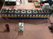
A pic of my full bank in parallel is pasted below. I forgot to ask for double bus bars, so ended up having to make small 'jumpers' out of some 4 awg I had laying around. Since all my balance charging will be fairly low current going forward, I'm not too worried about differences in resistance. For the final build, I've got 3/4" x 1/8" copper bar stock that I'll be cutting and drilling for the bus bars.

Thanks again to everyone who's commented. I really appreciate all the constructive feedback.

IMG_7541.JPG
 
A wee tip.
Once you have fully charged and saturated the cells (meaning that Amps taken is <2.5A and static) and you disconnect them all. Observe the settling & voltage drops. If "any" cell drops faster/deeper than the rest, you've identified a runner. This is what I observed through my own test processes.

I took one such and did deep discharge to 2.50, allowed to settle out which brought it to 2.60, then did a hard charge (cell only) starting at 40A and topping it to 3.60 and allowed to saturate. I then observed that it settled more in line with the others. Done this with 2 cells and got same result. Fluke, Oddity or just luck, I dunno. EVE 280's BTW.
That's exactly what I'll do Steve. I was planning on letting them settle as a parallel group for a few hours, then topping back up, and finally separating them out and closely monitoring voltage for the next 48 hrs. If I find a 'runner', i'll try the procedure you suggested.

What your preferred method for discharging individual cells?
 
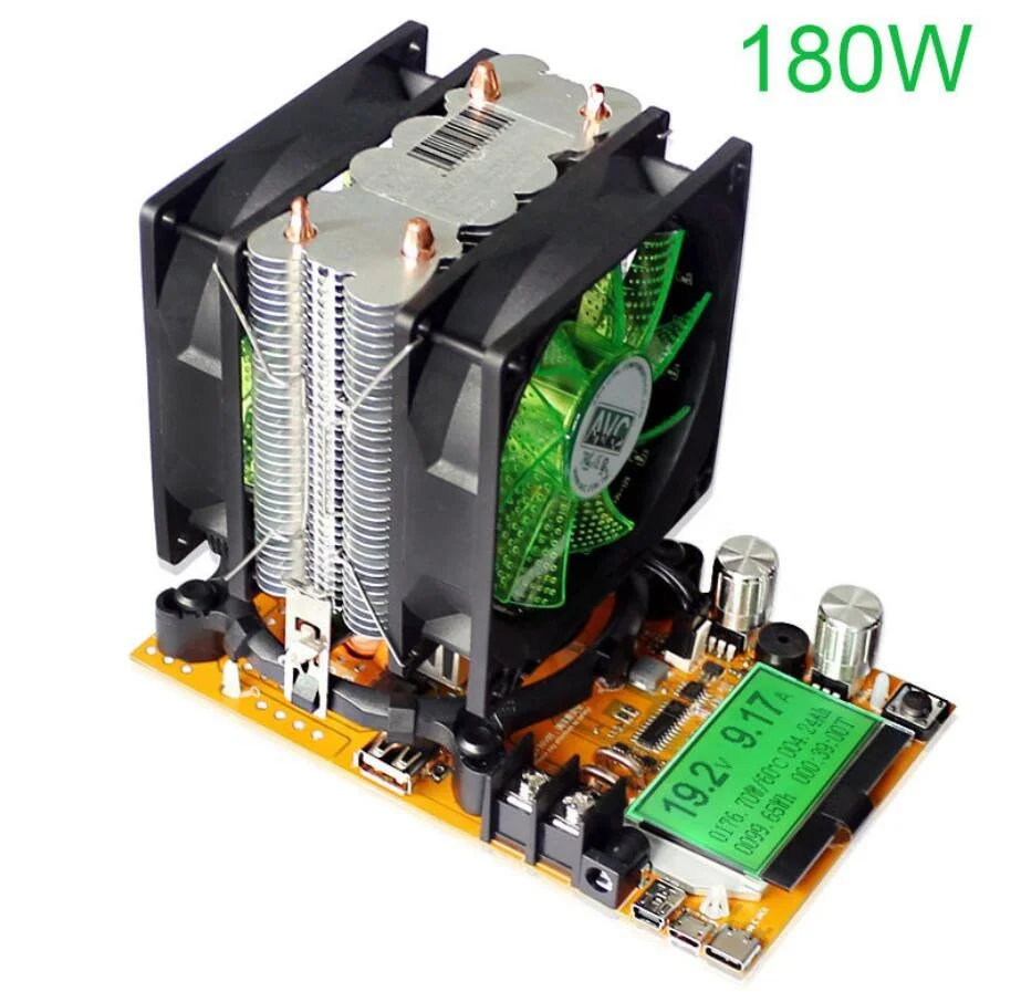
I have a 20A/180W Capacity tester for the general tests.

Hbff9d98553224db7833f69447e5f6055l.jpg

8 In 1 150w 180w Digital Battery Capacity Tester Voltmeter Adjustable Constant Current Electronic Load Charger Meter Indicator - Buy Digital Battery Capacity Tester,Usb Meter Indicator,External Battery Charger Product on Alibaba.com

Using 10G fine strand copper wire with crimped ring terminals for solid contact.

Note there is a newer version which has data-logging that can be connected to a PC.
 
Hi Everyone,

Starting a build thread now that my cells are officially on US soil. The pack will ultimately be configured in as 16s1P feeding two 48V 3000W Growatt inverters (set up as an off-grid, split-phase 120/240 system).

First off, here’s a summary of my Alibaba purchasing experience to date:
  • Vendor: Shenzhen Basen Technology Co., Ltd (contact: Sheila Chou)
  • Cells: Lishen 272 Ah (sold as Grade A), 16ea
  • Price paid: $75.20/cell + $394.00 shipping/tax/fees, Total cost: $1597
  • Order date: Nov 16, 2020
  • Shipment date: Nov 19, 2020 (to Wisconsin, USA)
  • Date of US arrival (port of LA): Dec 21st, 2020
  • Date transferred to FedEx: Jan 10, 2020
  • Date of receipt (expected): Jan 15, 2020 (total transit time: 57 days)
Note: I originally purchased EVE 280Ah cells, but was informed the day after I placed the order that those were out of stock and they would be shipping Lishen cells. I gave the go-ahead based on the generally positive feedback about Lishen cells on this forum.

Here’s my plan to get them up and running:
Step 1 – Top Balance: Parallel top balance using a Mean Well HRG-300-3.3 with Arduino control/monitoring. To minimize the risk of damaging all of my cells, I’m planning to start the process by taking groups of 4 cells to 3.55v. I’ll then parallel the entire group and top them off to 3.65v.​
Step 2 – Series Connect: Compress cells in groups of four using ¼” aluminum plates and ½” stainless steel cable ties. Series connect using bus bars made from 3/4” x 1/8” copper flat stock. I’m planning to try my hand at nickel plating the bars myself, but I may end up sending them out if that doesn’t go well.​
Step 3 – BMS Connection/Setup: Connect/configure TinyBMS s516 for battery management. I’m planning to use a separate port configuration with 5A SSRs switching the inverters off for LVD/HVD/LTD protection. Very excited to get the BMS up and running so I can start tinkering to determine functionality. Lots of analog and digital pins to play with, assuming I can figure out the programming.​
Step 4 – Capacity Testing: Use one of my Growatt inverters and a ~2600w load (~0.2C) to capacity test the bank.​
Step 5 – Battery Case: I’m planning to use a insulated/heated steel box for cell storage. A 16”x12”x30” ‘welders box’ with 1” of XPS insulation all around seems to be a very good fit for the cell configuration I’m using. Heat will come from four 12v silicone heating pads run in series off the 48v supply. Not settled on control system for that yet (Arduino vs. off-the-shelf PID vs. BMS control).​
Step 6 – Install & Test

Much more detail on each of these steps to follow, but please feel free to comment on anything listed above that doesn’t make sense.
I'm contemplating MPP 2424LV and Growatt 3000. Can you please comment on the Transfer Time from Battery/Solar to Grid? Will P. Showed the MPP has zero and his computers and routers stayed connected. What happens to the Growatt in that scenario? Zero Tranfer Time or does a computer turn off. Have yet to hear a Growatt owner first hand. All I see is the manual stating 10-20ms and saying it "should" stay on.

Thanks and nice work!
 
I have a 20A/180W Capacity tester for the general tests.

Hbff9d98553224db7833f69447e5f6055l.jpg

8 In 1 150w 180w Digital Battery Capacity Tester Voltmeter Adjustable Constant Current Electronic Load Charger Meter Indicator - Buy Digital Battery Capacity Tester,Usb Meter Indicator,External Battery Charger Product on Alibaba.com

Using 10G fine strand copper wire with crimped ring terminals for solid contact.

Note there is a newer version which has data-logging that can be connected to a PC.
Does yours have the same problem as mine?
Post in thread 'Eve 280AH capacity testing' https://diysolarforum.com/threads/eve-280ah-capacity-testing.16521/post-194973

I also have the new version you speak of, it also has a similar problem. It does however have sense wires, which means you can actually set an accurate cut off voltage.
 
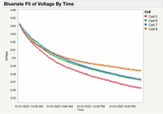
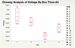
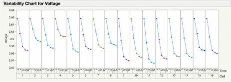
Top Balancing Update: It's now been 24 hours since I completed a top balance of the full group of 16 cells. As previously detailed, I took the full group slowly to 3.65v, then let the group settle in parallel for 2 hrs, then topped it back up to 3.65v. After that, I separated all cells and monitored voltage. For 4 of the cells, I hooked them up to an old Arduino set up to monitor voltage (one data point per min). Results from that tracking, as well as the individual measurements I took of all 16 cells are pasted below.

Bottom line, it looks 24hr settling voltage is ranging from 3.533 (cell 11) to 3.607 (cell 4). One interesting trend is that the boxes seem to be trending together, on average (cells 1 - 4 are from box 1, 5 - 8 from box 2, etc). This shown in the oneway plot on the top right. Not sure if i'm seeing a true difference in cell 'performance' vs. an artifact of the fact that i pre-charged each box of cells separately using an 'evolving' set of conditions.

In the top plot, cells 5 and 8 have corroded vents and scratched off QR Codes, while 6 and 7 were clean cells. Interesting that the 'best' and 'worst' from this group were the two corroded cells...

Very interested to hear thoughts on whether the variability in the data below is typical of a properly balanced set of prismatic cells. Should I take another crack at balancing, or are these good to go???

Picture3.png Picture5.png

Picture6.png
 
Last edited:
Top Balancing Update: It's now been 24 hours since I completed a top balance of the full group of 16 cells. As previously detailed, I took the full group slowly to 3.65v, then let the group settle in parallel for 2 hrs, then topped it back up to 3.65v. After that, I separated all cells and monitored voltage. For 4 of the cells, I hooked them up to an old Arduino set up to monitor voltage (one data point per min). Results from that tracking, as well as the individual measurements I took of all 16 cells are pasted below.

Bottom line, it looks 24hr settling voltage is ranging from 3.533 (cell 11) to 3.607 (cell 4). One interesting trend is that the boxes seem to be trending together, on average (cells 1 - 4 are from box 1, 5 - 8 from box 2, etc). This shown in the oneway plot on the top right. Not sure if i'm seeing a true difference in cell 'performance' vs. an artifact of the fact that i pre-charged each box of cells separately using an 'evolving' set of conditions.

In the top plot, cells 5 and 8 have corroded vents and scratched off QR Codes, while 6 and 7 were clean cells. Interesting that the 'best' and 'worst' from this group were the two corroded cells...

Very interested to hear thoughts on whether the variability in the data below is typical of a properly balanced set of prismatic cells. Should I take another crack at balancing, or are these good to go???

View attachment 34044 View attachment 34052

View attachment 34054
Well, interesting data points. Mine (so far) settle to 3.55 to 3.53 in 24 to 72 hours. I use my Riden set at 3.65 and let it turn off when .1 amps or lower is drawn, my Fluke says that is 3.652. So far I haven't had a cell settle to under 3.5 volts even after 3-4 days.
 
Top Balancing Update: It's now been 24 hours since I completed a top balance of the full group of 16 cells. As previously detailed, I took the full group slowly to 3.65v, then let the group settle in parallel for 2 hrs, then topped it back up to 3.65v. After that, I separated all cells and monitored voltage. For 4 of the cells, I hooked them up to an old Arduino set up to monitor voltage (one data point per min). Results from that tracking, as well as the individual measurements I took of all 16 cells are pasted below.

Bottom line, it looks 24hr settling voltage is ranging from 3.533 (cell 11) to 3.607 (cell 4). One interesting trend is that the boxes seem to be trending together, on average (cells 1 - 4 are from box 1, 5 - 8 from box 2, etc). This shown in the oneway plot on the top right. Not sure if i'm seeing a true difference in cell 'performance' vs. an artifact of the fact that i pre-charged each box of cells separately using an 'evolving' set of conditions.

In the top plot, cells 5 and 8 have corroded vents and scratched off QR Codes, while 6 and 7 were clean cells. Interesting that the 'best' and 'worst' from this group were the two corroded cells...

Very interested to hear thoughts on whether the variability in the data below is typical of a properly balanced set of prismatic cells. Should I take another crack at balancing, or are these good to go???

View attachment 34044 View attachment 34052

View attachment 34054
I forgot to add, yes. I think they are top balanced, worth trying a capacity test of the full bank.
 
Back
Top