diy solar

diy solar

16S Active Balancer just "exploded"?

Metero

New Member
Joined
Aug 17, 2021
Messages
11
Hello my friends,
quite new to DIY battery packs but I would say, that I am really sure what I am doing from an electrical perspective - until now ;).

I finished my first project with building a ~10KWh 16S 48V LiFePo4 battery for my 5KW hybid inverter which is connected to 10 of 310W mono-solarpanels. So far so good. System was running quite well with the LiFePo4 pack for several weeks until I noticed that the cells getting quite unbalanced when going from ~80% to 100% SOC - even I initially top-balanced them at the beginning. So I just ordered an 16S active balancer from AliExpress (Heltec: https://www.aliexpress.com/item/4000938109615.html?spm=a2g0s.9042311.0.0.701c4c4dGOoFQ9) with a maximum balance current of 5A - which seemed really nice and useful to me.
When it arrived a week ago I instantly installed this little PCB with its wires as explained in the manual (https://diysolarforum.com/resources/heltec-capacitive-active-equalization-active-balancer.204/). So connecting the first B- wire to the same battery pole as the BMS (Daly BMS 16S 200A) and then connecting each positive pole in the correct order. Before connecting the balancer I measured each connector/cable to ensure the correct connection order - everything fine, same procedure as connecting the BMS.
Now after 3 days of working really well and without any issues, I decided to make a stress test of the whole system with the battery at 100% SOC. I started with 1KW consumption (~20A) up to 4KW (~83A). When I plugged in the last device with 2.2 KW consumption the BMS did cut off the whole pack. While this happened I noticed the BMS showing one cell with >4V for around 2 seconds. So... I tried the same test again. But now (also the BMS did cut off the battery) the balancer short-circuted with a little spark and a few seconds later (when the battery pack was definitly cutted of) 3 capacitors of the PCB just "popped" / exploded off. That was really a shocking moment and I thought "alright, thats it, everything will be broken now". After I securely disconnected the balancer, I checked every cell and the BMS and everthing seems alright for now - exept the balancer, which is completely destroyed.

NOW the final questions: how the f*ck could this happen? Was it my fault or was the balancer faulty since the beginning? I was hitting 80A to 90A consumption, was it too much for the balancer? What is the maximum consumption you can draw with an active balancer?

Thank you all in advance for your expertise on this topic!

Best regards
Paul
 
Last edited:
This is the 1st time I have heard of such a thing happening.
Did you wire the BMS Harness Leads to Ring Terminals and the Balancer heads to Ring Terminals and have them situated on the same cell terminals ?
 
I previous noted that electrolyte capacitor charge transfer active balancers work well but reliability of electrolytic capacitors subjected to high ripple current is questionable.

Don't condemn active balancers in general.

If you accidentally reversed voltage to an electrolytic cap it is almost instantly toast.

If you have rapidly changing large current loads on the battery by inverter it fluxuates cell voltage. A cap based balancer can pick up a charge when cell voltage is at its highest voltage level, under light external load current, then dump its charge when inverter load current spikes and the cell the cap is dumping to is at its lowest voltage due to external current loading. This increases the ripple current on the electrolytic caps. A sinewave inverter has a sinewave shaped DC input current profile with a period of twice the AC output frequency so just a constant AC heavy inverter load will have a high battery ripple current varying instantaneous load current on battery.

Since active balancers operate continously, and in flatter portions of discharge curve, they must be able to accurately represent the cell voltage comparison in the operating environment of changing inverter loads and charging currents. The only reliable way to do this is a near instantaneous and simultaneous snap-shot of all cells so all cells are measured with the same external instant-in-time current loading conditions.

For a leap-frog type active balancer (one that has overlapping charge transfer between adjacent cells) the voltage measurement does not have to be an actual reading of voltage, just a simple comparitor saying which of the two adjacent cells' voltage is greater or less then the other. However this also must be done simultaneously for all cells at same instant in time.
 
Before connecting the balancer I measured each connector/cable to ensure the correct connection order - everything fine, same procedure as connecting the BMS.
This sounds right and if your test showed 3.2V per cell increase across the battery that's perfect.

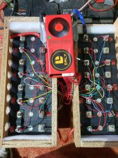
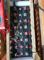
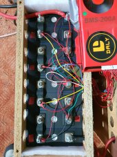
But, happen to have a pic of your setup? Having a few hundred eyes looking at something usually finds something if it is out of place or suspect.
 
NOW the final questions: how the f*ck could this happen? Was it my fault or was the balancer faulty since the beginning? I was hitting 80A to 90A consumption, was it too much for the balancer? What is the maximum consumption you can draw with an active balancer?

Can you post pics from your system?
Maybe we can spot an error or a reason for this mishap
 
This is the 1st time I have heard of such a thing happening.
Did you wire the BMS Harness Leads to Ring Terminals and the Balancer heads to Ring Terminals and have them situated on the same cell terminals ?
I couldn't find anything like that on google too :D
So I wired and installed the balancer exactly the same as the BMS with its own ring terminals but on the same cell terminals. So the wiring cannot be the problem in my opinion. And without any heavy load, the balancer was working as expected.
 
Will provide pictures asap! Thank you all for your interest and willingness to help!
 

The order in the terminals is not ideal.
The V values can be wrong.
Active balancer can not work as designed without direct connection to busbar or other good conductor (other lug).


1628528723242-png.59384
 
Being honest here... I had one of these boards that blew two out of the three capacitors off in one line. Turns out... I misconnected the cells. It's how I learnt the importance of metering out the plugs on stuff like that before connecting.
 
@Metero - don't know if you're thinking of repairing the module or not, but I found that these polymer capacitors aren't as easy to come by as ordinary aluminum electrolytics. Also not as easy to desolder, as there are a lot of components commoned together and they will all get hot
 
The '2200' 6.3v caps in the picture are 2200 uF 6.3v rated aluminum electrolytics. You won't find that in a polymer cap.

The best you can do is look for a 2200 uF with same diameter but taller with a higher voltage rating, like 10v or 15v rating. The higher the voltage rating the lower the internal resistance and more voltage margin will have a bit better reliability.
 
Last edited:
Being honest here... I had one of these boards that blew two out of the three capacitors off in one line. Turns out... I misconnected the cells. It's how I learnt the importance of metering out the plugs on stuff like that before connecting.
Hi jimbob420, like I wrote, I did check the plugs before connecting and everything was and is correct :/

I noticed another odd thing, while testing the battery pack again without the balancer. Same power consumption as when the capacitors exploded: 4KW. While doing this I checked the values of the BMS and saw that one cell drifted off too much. While (I think) every other cell was around 3.2-3.1V that one cell was shown with 2.7V. In that moment I also noticed some heat generation one the negative terminal of that cell and instantly shutdown everything. So... multiple problems here: why is that one cell so much drifting? Why did the BMS did not cutoff when the differential voltage was over 0.25V (like I entered it in the setting of the BMS)? Is the cell broken? Was it broke befor the balancer exploded? So is it the reason for the balancer to fail? Or did the balancer cause any problem to the cell?

Next steps: disconnecting every connection, cleaning everything, reconnect, stress test while checking all cell values and see, if the drift still appears and how the BMS react.

It is possible there is a bad connection.
Terminals and busbars polished? Conductive grease? Enough force in the nut?
And the order on top of the terminals is wrong. Fix that first :)
 
It is possible there is a bad connection.
Terminals and busbars polished? Conductive grease? Enough force in the nut?
And the order on top of the terminals is wrong. Fix that first :)
Of course I will change the terminals first ;)

Yes, polished every busbar and lug and also I used good conductive grease (which I think can also cause some problem, maybe I used too much?): https://www.amazon.de/gp/product/B0...in_title_o09_s00?ie=UTF8&language=en_GB&psc=1

Nut force (lol? :D) should be also perfect, checked every connection multiple times if its tight enough.
 
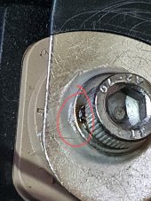
For full documentation - this is a picture of the negative terminal of the mentioned cell 4 (counted from the beginning of the right top pack) after the second stress test without the balancer. This was the indicator of heat generation as it colored dark with a little bit of smoking. But the connection is definetely not soldered, I checked the screw and you can loose it.
20210817_194547.jpg
 
Of course I will change the terminals first ;)

Yes, polished every busbar and lug and also I used good conductive grease (which I think can also cause some problem, maybe I used too much?): https://www.amazon.de/gp/product/B0...in_title_o09_s00?ie=UTF8&language=en_GB&psc=1

Nut force (lol? :D) should be also perfect, checked every connection multiple times if its tight enough.

I am not sure but one comment there says it is not a conductive paste. Only an alu oxidation blocker.
 
Back
Top